So I'm bedding my new Farrell G force scope base to my Savage 110FP using Devcon, and I've run into an issue. After the bedding cures I pop it loose and clean off the rifle and base of all the release agent (kiwi shoe polish) and play-doh. I go to mount the base and after it's torqued I look at the rear of the base and there's a gap on the right side. it's not a big gap it's just enough to slip a piece of paper underneath, it slides all the way to the mounting screws, but it's enough to bother me so I decide to redo the bedding. well this time I paid close attention to how much release agent I put on the receiver, 24 hours later and the same damn thing happens, just enough gap to slip a piece of paper under the right side. so before I redo it again expecting a different result (I know insanity) does anyone have suggestions as to why this is happening? I've bedded 2 bases before and didn't have any issues, I can post pictures if need be.
Join the Hide community
Get access to live stream, lessons, the post exchange, and chat with other snipers.
Register
Download Gravity Ballistics
Get help to accurately calculate and scope your sniper rifle using real shooting data.

Install the app
How to install the app on iOS
Follow along with the video below to see how to install our site as a web app on your home screen.
Note: This feature may not be available in some browsers.
You are using an out of date browser. It may not display this or other websites correctly.
You should upgrade or use an alternative browser.
You should upgrade or use an alternative browser.

Gunsmithing Scope base bedding issues
- Thread starter sagillman
- Start date
When you apply torque could that be bending something? Given any thought to lightly snugging down all four screws before you start to apply torque? Any chance that after you remove the shoe polish, the base is in a different place - shifted forward or to one side? Any chance you used too much shoe polish? Could the base have a twist in it? I use the commercial release compound from Brownells. After I do my bases, no base metal touches receiver metal - there is a thin but not zero coating of bedding compound between the base and the receiver.
Whole point to bedding a base is to do it tension free. I'd bet you aare snuggin up the "loose" end of the base too much. Sort out which side is higher. Front/rear? Then only snug up the tight side so that bedding actually gets to fill the voids on that bad end. This will solve the mating issue instead of being squished out.
c.
c.
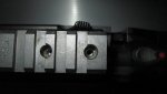
I did the rear of the base. I plugged the rear holes in the base and receiver and just snugged the front 2 base screws. I figured out the issue anyways, if I snug the front base screws and look through the rear base holes they are off to the left side of the receiver threads. I have to start them all at the same to get them to thread in and I guess it's pulling the rear of the base to the right. here are a couple pictures
Attachments
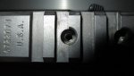
Your base holes were drilled off center and arn't lined up. You will need to have them drilled and tapped to 8/40 and centered. A smith should do it for 75$ or so. Right now your scope will be pointing way off to one side and you probably wont have enough windage in your scope.
Yeah, the only problem is there are no smiths around here(that I know of) that do this type of work.Your base holes were drilled off center and arn't lined up. You will need to have them drilled and tapped to 8/40 and centered. A smith should do it for 75$ or so. Right now your scope will be pointing way off to one side and you probably wont have enough windage in your scope.
We do it.
$100 for 4 holes.
difference with us is were not using a drill which just follows the same hole. We interpolate them in a cnc and thread mill the new threads.
perfect location everytime.
$100 for 4 holes.
difference with us is were not using a drill which just follows the same hole. We interpolate them in a cnc and thread mill the new threads.
perfect location everytime.
We do it.
$100 for 4 holes.
difference with us is were not using a drill which just follows the same hole. We interpolate them in a cnc and thread mill the new threads.
perfect location everytime.
Can you guys do a Savage 110, flat rear?
Thanks
We do it.
$100 for 4 holes.
difference with us is were not using a drill which just follows the same hole. We interpolate them in a cnc and thread mill the new threads.
perfect location everytime.
I sent you a pm chad.
Well I shipped everything to Chad this afternoon, so I'm confident it's going to be fixed right.
Out of all the actions that I've ever performed a scope base hole enlargement to, the 1903 SpgFld has been by far the most delicate/challenging to date.
Reason is they are hard as wood pecker lips. The steel is just hard/tough shit. No other way to describe it.
That said, the owner of this particular action said it best I think, "after watching this take place, I wanted to go home and throw rocks at my mill."
Right tools for the job make this stuff a whole lot simpler. We have those tools, so I'm confident we can tune your Savage up for you.
Happy to help.
C.
B/A arrived this morning. Problem solved. Base holes on the receiver were out a smidge, but the bigger issue was in the base. A little machine work, some blasting, and a quick dunk in the park tank has it all back together good as new.
Leaves in the am, thanks Steve.
C.
Leaves in the am, thanks Steve.
C.
Thanks Chad, I never would have guessed the dang base I paid so much for would have been an issue, but like you said on the phone Savage likes to change stuff and not let anyone know about it. I appreciate you getting it all straightened out for me and the lightning fast turnaround, you have earned a customer for life.B/A arrived this morning. Problem solved. Base holes on the receiver were out a smidge, but the bigger issue was in the base. A little machine work, some blasting, and a quick dunk in the park tank has it all back together good as new.
Leaves in the am, thanks Steve.
C.
Whole point to bedding a base is to do it tension free. I'd bet you aare snuggin up the "loose" end of the base too much. Sort out which side is higher. Front/rear? Then only snug up the tight side so that bedding actually gets to fill the voids on that bad end. This will solve the mating issue instead of being squished out.
c.
"Interpolate".....that's fancy. I bet a dollar to a hole in a donut that 9/10 people need to Wikipedia that one. Just curious when you do interpolate the position(s), what points are you using as reference? You would need two fixed point to for the "line" to interpolate between.
Next week we will cover "extrapolate".....lol.
Using Helical Interpolation To Make Large-Diameter Holes : Modern Machine Shop
Example. 1.5" ID bore being "interpolated" with a 1/2" EM. .200" pitch on the helix. This version uses splines (small line segments) to generate the arcs. You can also post it with actual arc movements. Makes the code much more consolidated and its easier on older machines with brushed servo motors
%
O0( T )
( DATE=DD-MM-YY - 02-07-14 TIME=HH:MM - 07:13 )
( NC FILE - C:\USERS\CHAD\DOCUMENTS\MY MCAMX5\MILL\NC\T.NC )
( MATERIAL - ALUMINUM INCH - 2024 )
( T1 | | H1 )
G20
G0 G17 G40 G49 G80 G90
T1 M6
G0 G90 G54 X0. Y0. A0. S9500 M3
G43 H1 Z.25
Z.1
G1 Z0. F50.
G3 X-.25 Y-.25 I0. J-.25 F100.
X0. Y-.5 I.25 J0.
G1 X.0413 Y-.4983 Z-.0026
X.0823 Y-.4932 Z-.0053
X.1227 Y-.4847 Z-.0079
X.1623 Y-.4729 Z-.0105
X.2008 Y-.4579 Z-.0132
X.238 Y-.4397 Z-.0158
X.2735 Y-.4186 Z-.0184
X.3071 Y-.3946 Z-.0211
X.3386 Y-.3679 Z-.0237
X.3679 Y-.3386 Z-.0263
X.3946 Y-.3071 Z-.0289
X.4186 Y-.2735 Z-.0316
X.4397 Y-.238 Z-.0342
X.4579 Y-.2008 Z-.0368
X.4729 Y-.1623 Z-.0395
X.4847 Y-.1227 Z-.0421
X.4932 Y-.0823 Z-.0447
X.4983 Y-.0413 Z-.0474
X.5 Y0. Z-.05
X.4983 Y.0413 Z-.0526
X.4932 Y.0823 Z-.0553
X.4847 Y.1227 Z-.0579
X.4729 Y.1623 Z-.0605
X.4579 Y.2008 Z-.0632
X.4397 Y.238 Z-.0658
X.4186 Y.2735 Z-.0684
X.3946 Y.3071 Z-.0711
X.3679 Y.3386 Z-.0737
X.3386 Y.3679 Z-.0763
X.3071 Y.3946 Z-.0789
X.2735 Y.4186 Z-.0816
X.238 Y.4397 Z-.0842
X.2008 Y.4579 Z-.0868
X.1623 Y.4729 Z-.0895
X.1227 Y.4847 Z-.0921
X.0823 Y.4932 Z-.0947
X.0413 Y.4983 Z-.0974
X0. Y.5 Z-.1
X-.0413 Y.4983 Z-.1026
X-.0823 Y.4932 Z-.1053
X-.1227 Y.4847 Z-.1079
X-.1623 Y.4729 Z-.1105
X-.2008 Y.4579 Z-.1132
X-.238 Y.4397 Z-.1158
X-.2735 Y.4186 Z-.1184
X-.3071 Y.3946 Z-.1211
X-.3386 Y.3679 Z-.1237
X-.3679 Y.3386 Z-.1263
X-.3946 Y.3071 Z-.1289
X-.4186 Y.2735 Z-.1316
X-.4397 Y.238 Z-.1342
X-.4579 Y.2008 Z-.1368
X-.4729 Y.1623 Z-.1395
X-.4847 Y.1227 Z-.1421
X-.4932 Y.0823 Z-.1447
X-.4983 Y.0413 Z-.1474
X-.5 Y0. Z-.15
X-.4983 Y-.0413 Z-.1526
X-.4932 Y-.0823 Z-.1553
X-.4847 Y-.1227 Z-.1579
X-.4729 Y-.1623 Z-.1605
X-.4579 Y-.2008 Z-.1632
X-.4397 Y-.238 Z-.1658
X-.4186 Y-.2735 Z-.1684
X-.3946 Y-.3071 Z-.1711
X-.3679 Y-.3386 Z-.1737
X-.3386 Y-.3679 Z-.1763
X-.3071 Y-.3946 Z-.1789
X-.2735 Y-.4186 Z-.1816
X-.238 Y-.4397 Z-.1842
X-.2008 Y-.4579 Z-.1868
X-.1623 Y-.4729 Z-.1895
X-.1227 Y-.4847 Z-.1921
X-.0823 Y-.4932 Z-.1947
X-.0413 Y-.4983 Z-.1974
X0. Y-.5 Z-.2
X.0413 Y-.4983 Z-.2026
X.0823 Y-.4932 Z-.2053
X.1227 Y-.4847 Z-.2079
X.1623 Y-.4729 Z-.2105
X.2008 Y-.4579 Z-.2132
X.238 Y-.4397 Z-.2158
X.2735 Y-.4186 Z-.2184
X.3071 Y-.3946 Z-.2211
X.3386 Y-.3679 Z-.2237
X.3679 Y-.3386 Z-.2263
X.3946 Y-.3071 Z-.2289
X.4186 Y-.2735 Z-.2316
X.4397 Y-.238 Z-.2342
X.4579 Y-.2008 Z-.2368
X.4729 Y-.1623 Z-.2395
X.4847 Y-.1227 Z-.2421
X.4932 Y-.0823 Z-.2447
X.4983 Y-.0413 Z-.2474
X.5 Y0. Z-.25
X.4983 Y.0413 Z-.2526
X.4932 Y.0823 Z-.2553
X.4847 Y.1227 Z-.2579
X.4729 Y.1623 Z-.2605
X.4579 Y.2008 Z-.2632
X.4397 Y.238 Z-.2658
X.4186 Y.2735 Z-.2684
X.3946 Y.3071 Z-.2711
X.3679 Y.3386 Z-.2737
X.3386 Y.3679 Z-.2763
X.3071 Y.3946 Z-.2789
X.2735 Y.4186 Z-.2816
X.238 Y.4397 Z-.2842
X.2008 Y.4579 Z-.2868
X.1623 Y.4729 Z-.2895
X.1227 Y.4847 Z-.2921
X.0823 Y.4932 Z-.2947
X.0413 Y.4983 Z-.2974
X0. Y.5 Z-.3
X-.0413 Y.4983 Z-.3026
X-.0823 Y.4932 Z-.3053
X-.1227 Y.4847 Z-.3079
X-.1623 Y.4729 Z-.3105
X-.2008 Y.4579 Z-.3132
X-.238 Y.4397 Z-.3158
X-.2735 Y.4186 Z-.3184
X-.3071 Y.3946 Z-.3211
X-.3386 Y.3679 Z-.3237
X-.3679 Y.3386 Z-.3263
X-.3946 Y.3071 Z-.3289
X-.4186 Y.2735 Z-.3316
X-.4397 Y.238 Z-.3342
X-.4579 Y.2008 Z-.3368
X-.4729 Y.1623 Z-.3395
X-.4847 Y.1227 Z-.3421
X-.4932 Y.0823 Z-.3447
X-.4983 Y.0413 Z-.3474
X-.5 Y0. Z-.35
X-.4983 Y-.0413 Z-.3526
X-.4932 Y-.0823 Z-.3553
X-.4847 Y-.1227 Z-.3579
X-.4729 Y-.1623 Z-.3605
X-.4579 Y-.2008 Z-.3632
X-.4397 Y-.238 Z-.3658
X-.4186 Y-.2735 Z-.3684
X-.3946 Y-.3071 Z-.3711
X-.3679 Y-.3386 Z-.3737
X-.3386 Y-.3679 Z-.3763
X-.3071 Y-.3946 Z-.3789
X-.2735 Y-.4186 Z-.3816
X-.238 Y-.4397 Z-.3842
X-.2008 Y-.4579 Z-.3868
X-.1623 Y-.4729 Z-.3895
X-.1227 Y-.4847 Z-.3921
X-.0823 Y-.4932 Z-.3947
X-.0413 Y-.4983 Z-.3974
X0. Y-.5 Z-.4
X.0413 Y-.4983 Z-.4026
X.0823 Y-.4932 Z-.4053
X.1227 Y-.4847 Z-.4079
X.1623 Y-.4729 Z-.4105
X.2008 Y-.4579 Z-.4132
X.238 Y-.4397 Z-.4158
X.2735 Y-.4186 Z-.4184
X.3071 Y-.3946 Z-.4211
X.3386 Y-.3679 Z-.4237
X.3679 Y-.3386 Z-.4263
X.3946 Y-.3071 Z-.4289
X.4186 Y-.2735 Z-.4316
X.4397 Y-.238 Z-.4342
X.4579 Y-.2008 Z-.4368
X.4729 Y-.1623 Z-.4395
X.4847 Y-.1227 Z-.4421
X.4932 Y-.0823 Z-.4447
X.4983 Y-.0413 Z-.4474
X.5 Y0. Z-.45
X.4983 Y.0413 Z-.4526
X.4932 Y.0823 Z-.4553
X.4847 Y.1227 Z-.4579
X.4729 Y.1623 Z-.4605
X.4579 Y.2008 Z-.4632
X.4397 Y.238 Z-.4658
X.4186 Y.2735 Z-.4684
X.3946 Y.3071 Z-.4711
X.3679 Y.3386 Z-.4737
X.3386 Y.3679 Z-.4763
X.3071 Y.3946 Z-.4789
X.2735 Y.4186 Z-.4816
X.238 Y.4397 Z-.4842
X.2008 Y.4579 Z-.4868
X.1623 Y.4729 Z-.4895
X.1227 Y.4847 Z-.4921
X.0823 Y.4932 Z-.4947
X.0413 Y.4983 Z-.4974
X0. Y.5 Z-.5
G3 X-.5 Y0. I0. J-.5 F30.
X0. Y-.5 I.5 J0.
X.5 Y0. I0. J.5
X0. Y.5 I-.5 J0.
X-.25 Y.25 I0. J-.25
X0. Y0. I.25 J0.
G0 Z.25
M5
G91 G28 Z0.
G28 X0. Y0. A0.
M30
%
Last edited:
"Interpolate".....that's fancy. I bet a dollar to a hole in a donut that 9/10 people need to Wikipedia that one. Just curious when you do interpolate the position(s), what points are you using as reference? You would need two fixed point to for the "line" to interpolate between.
Next week we will cover "extrapolate".....lol.
How many points of reference do you need if that "line" is helical?

How many points of reference do you need if that "line" is helical?
Well, I'm no machinist, but I have spent the better part of my life in mathematics and applied engineering so the simple answer would be lines are not helical. Helical implies an arc or non-linear. The basic definition of interpolate (I'm not quoting a dictionary; just paraphrasing) is is locating a single point between two additional points that exist on a "line". The basis being constant slope over the distance. That being said, the method is practically used to "estimate" points on arcs or non-linear functions by assuming a straight line over a small incremental distance of the arc or function. Somewhat similar to integration by parts (non-trigometric).
So for a helical interpolation the number of points is not fixed. The more points used, the more accurate the interpolated value is to the true helical function, i.e. Less error.
I just thought it refreshing to see interpolation being used at all in practice. I don't hear about it very often outside technical settings.
Chad:
I can see the incremental slopes used between several of your points, or round value points. They follow steady incremental changes in position. As in my former response, I can see why you have so many points interpolated greater accuracy along the arcs. Seems you are using base position increments of .0413" on X and Y with .0026" on Z (depth I assume).
Thanks. It's interesting.
Points are good but one must never assume that points make the difference. Encoder resolution, machine ball screw backlash, tool deflection, and brushed/brushless servo motors are all issues that'll make you go batchit crazy when they aren't right.
Example. On the kitty i can run a "circ-n-terp" at any feed rate i want for the most part. On the old Haas about 50ipm is all she's good for. itll rattle the fillings out of your teeth if you try to push it harder. 1992 vs the modern world. Cool chit.
Example. On the kitty i can run a "circ-n-terp" at any feed rate i want for the most part. On the old Haas about 50ipm is all she's good for. itll rattle the fillings out of your teeth if you try to push it harder. 1992 vs the modern world. Cool chit.
Last edited:
Points are good but one must never assume that points make the difference. Encoder resolution, machine ball screw backlash, tool deflection, and brushed/brushless servo motors are all issues that'll make you go batchit crazy when they aren't right.
Example. On the kitty i can run a "circ-n-terp" at any feed rate i want for the most part. On the old Haas about 50ipm is all she's good for. itll rattle the fillings out of your teeth if you try to push it harder. 1992 vs the modern world. Cool chit.
Spoken like a true lefty;-) Too bad you can't vote for o again;-)
Using your hands on to contradict EKG's knowledge works in holes like this. Not many understand what's being said. Reminds me of the thread about truing actions and you alinsky'd into your buddy's bicycle shop;-) Now is your chance to tell us how round the hole is;-)
I don't have a clue what interpolation is but I can tell you that if a mathematician says it only pertains to points BETWEEN 2 points that create a line and you throw up your program to impress. I'm going to call BS!
And iF you expect me to believe that running over 50 ipm cutting an 8-40 thread will rattle your teeth, you are stupider that I thought;-)
Reread your gibberish and see that you are ironing out the helix to make it easier to program.
I thought we were trying to get 4 holes to line up on th CL of the action? ;-)
I thought we were trying to get 4 holes to line up on th CL of the action? ;-)
Nobody is ironing anything. If anything it's the polar opposite of what your implying. A splined helix is a hell of a lot more complicated to program than an arc movement. Why? It's exponentially more typing. Arcs are far simpler.
Now, here's the little lesson that's really important. Source code vs "fat fingering" a program at the control on the machine. I'm reading your post with the understanding that you think I'm manually typing all this shit out. Let me explain something to you.
For a job shop or tool room doing a one off part/operation that'll never be seen again, that's fine. Bang away on the control with your index finger and just get through the job. I get that. However, if its something you do over and over again. (it can be anything, doesn't matter) the shops that engage/embrace this practice will eventually find a brick wall to run face first into.
Why?
Because the source code was never updated to what's being made on the floor. If it's part of an assembly and a revision comes down the pipe, all that "gibbrish" in the control and/or the ISO file stored on a disk somewhere becomes instantly obsolete. SOURCE code saves your ass. Drive your process from the beginning. Failure to do so is pure laziness. Lazy in the essence that you failed to take the time to become fluent with the CAD/CAM package you have OR your just too lazy to go back and do the job the right way by updating the CAD drawing to reflect the change made by the engineer/designer.
What this means is the job MUST be updated in the drawings, the CAD file, and then the code that goes into the machine that actually makes the part.
What I'm stating is I rarely "fat finger" a program in the control because doing so means I'm cutting my own legs off.
Next-
Choice between splined or arc output is as simple as checking a box in the parameter setup portion of an operation. Has nothing to do with making one easier than another. I chose splines for this discussion because it seemed more relevant to the topic. If you'd like to see arc movements then here:
%
O0000(T)
(MACHINE = KITAMURA VERTICAL MILL)
(MATERIAL= ALUMINUM INCH - 2024)
(TIME=06:44 - JUL-03-14)
M1
G20
G91 G28 Z0.
T1 M6 (DEFINE TOOL NAMES)
G0G17G94G40G49G80G90
G0 G90 G54 J2 X0. Y0. A0. C0. S15000 M3
G43 H0 Z.25
Z.1
G1 Z0. F20.
G3 X-.25 Y-.25 I0. J-.25 F150.
X0. Y-.5 I.25 J0.
Z-.1 I0. J.5
Z-.2 I0. J.5
Z-.3 I0. J.5
Z-.4 I0. J.5
Z-.5 I0. J.5
Z-.6 I0. J.5
Z-.7 I0. J.5
Z-.8 I0. J.5
Z-.9 I0. J.5
Z-1. I0. J.5
Z-1.1 I0. J.5
Z-1.2 I0. J.5
X.5 Y0. Z-1.225 I0. J.5
X0. Y.5 Z-1.25 I-.5 J0.
I0. J-.5
X-.25 Y.25 I0. J-.25
X0. Y0. I.25 J0.
G0 Z.25
G91 G28 Z0. M5
G90 G17
G59 J1 X0. Y0.
M30
%%
Whole lot less going on here. Notice in the first example that I only went to a depth of a half inch. (Z-.5) Here I went to a depth of -1.25. If I'd of done that in the first, the code would be ridiculously long. -as if it wasn't anyway Why? Think of how many points there are to run between each little spline segment just to get from 0 to 360*. Arcs are much simpler/easier to program.
So, halfassing? Hardly.
As far as accuracy goes, again, there's dynamics to this far beyond the posting of impressive looking code. The big ones were already mentioned. Either method is an acceptable way to machine the part.
What it really comes down to is efficiency and the type of firmware installed in the control of the machine doing the work. CNC machines only have so much memory. The way information is stored/used in a CNC is vastly different than a PC on a desk. It's more like RAM. A 1TB HD for a PC is now a couple hundred bucks. In a CNC such a thing could likely be a 6 figure upgrade. -IF its even available. I personally have never seen it but there's a whole lot of new stuff out there that I'm not aware of too so who knows.
Next, firmware. Some machines don't support arc movements with a change in the Z axis. They can only cut a circle. For those that don't, the "fix" is to generate the arcs as splines. Both my machines support arc outputs so its a win/win because I'm not burning up memory or fighting the pulsing issues with brushed servos.
One can setup a machine DNC (where the machine becomes slaved to the computer- Direct Numeric Control) But its a pain in the ass when you have a lot of parts to make with short cycle times. You have to load/set it up every time. For a production job the optimum solution is to have it stored in the control. This means being efficient in how you program to ensure it all fits in the machine. Otherwise your just shooting yourself in the foot.
That covers that, onto the next item:
Because spline driven code is so "busy' it means a shit load of pulses being sent from encoders (positioning devices) and servo cards (card that sends the pulse to the servo motor that moves the machine). Whether its a hole that's 10" in diameter or one that is only .140" matters little. A pulse is a pulse and a couple .001's doesn't change anything. So, YES, an 8-40 hole boring or thread mill op will mean the machine (my Haas) won't like it if I try to push it past 50 ipm.
The function of spindle rpm also comes into play. The ol Haas only has a 6500rpm spindle. The Kitty has much more.
SFM in a given material for a given tool grade dictates how quickly a job can get done. The thread mills I use are good. Really good in fact. If I have the spindle speed, I can push them to around 600 SFM if I want to. 50ipm is very possible. Do I use it when doing action work? No, I want the tool to last as they aren't cheap and were working with heat treated steels. Why burn them up? If I were doing a production job in aluminum I couldn't run them fast enough.
So, the tool will do it so long as the machine has the ability to accurately process the program onto the table where the work gets done. The Haas I have won't do this at lightening speed. The Kitamura will however. It's two totally different classes of machines.
In closing:
Bottom line is this. There's a whole lot more to this that often times I just don't take the time to explain. Why? Time is money and most here won't benefit from it because they don't have the equipment to try it out on anyway. -Then I just get labeled as a blow hard and chest beater so why bother. I embraced this conversation with a lot of detail because I was asked a very relative question by someone with the education to use and interpret it.
IF you don't have that then making bold statements about someone being lazy or full of shit only illustrates your inexperience with this side of the manufacturing world.
Happy 4th.
C.
Last edited:
Happy 4th to you!
Lotta time is money to alinsky your way out of overstating the teeth rattle. If it makes your Haas walk across the floor, Please! show us some vid;-)
Lotta time is money to alinsky your way out of overstating the teeth rattle. If it makes your Haas walk across the floor, Please! show us some vid;-)
What I cant believe is someone calling Chad stupid
you and me both.
you and me both.
Get off your knees guys, He's not God.
We're all stupid if you boil it down. Otherwise we would all be driving vehicles that run off water or nukes ;-)
My argument is Chad knows most of us don't know what he's talking about when it comes to G code so we just read over it. Seems EKG has a grip on #s so he spoke up.
My mill has a DNC to borrow Chad's terminology. It has a test run button that goes thru the prog. at 100 ipm. It seems pretty angry when there is a bolt hole pattern or an arc that has ending points. You could even convince yourself that you hear a boom when it stops at the programmed point. However, threading a hole is the same as milling a pocket. The servos run magically smooth.
That aside, the program we are talking about is 4 holes in a line with a milled (pocket) at each point. You get 1 jolt to Zero (1st hole) Pause (threading) jolt 2 (2nd hole) Etc. Even it you throw in a jolt for the Z coming out of the hole, I wouldn't consider it teeth rattling.
If you can grasp that, ask yourself why you would run a program 50 ipm unless you were into multi setup production or the cutter mfg recommended it. As Chad said, they aren't cheap.
It takes more time to set up the action than it takes to punch the holes unless you just clamp it in a vise with a level.
I live in Tx and I know BS when I see it. ;-)
As a buddy stated this morning. Arguments on the Internet are like the special olympics. Even when you win your still a retard.
Uncle. You win grand wizard.
c.
Uncle. You win grand wizard.
c.
Last edited:
Well played saul! It's not about winning but setting the record straight.
Care to enlighten us on how your worn out Hass jumps across the floor when you cut a pocket with a thread mill?
Care to enlighten us on how your worn out Hass jumps across the floor when you cut a pocket with a thread mill?
Similar threads
- Replies
- 16
- Views
- 675