Gunsmithing chamber flush system "build thread"

300sniper

Gunny Sergeant
Full Member
Minuteman
Jan 17, 2005
3,438
26
Greenwood, Ca
i had some of these posts on another thread. i decided to start my own thread instead of completely hijacking the other one.


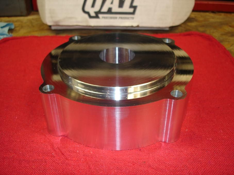
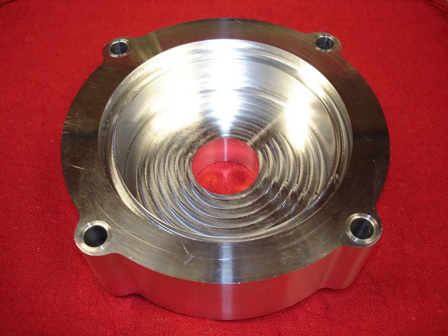
i finally got around to making parts for my system.

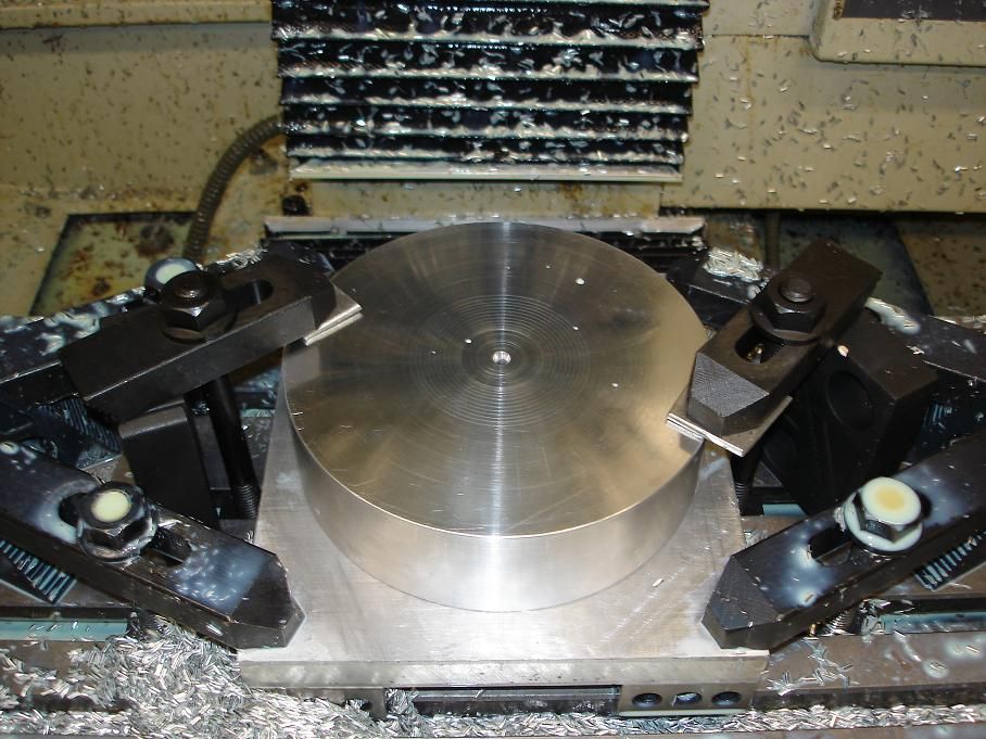
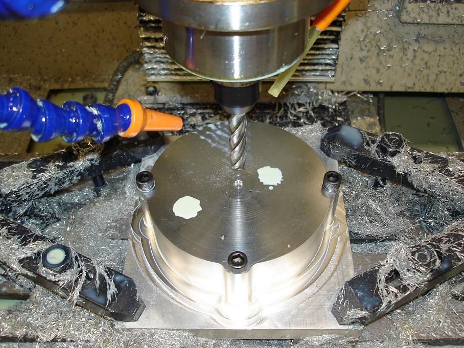
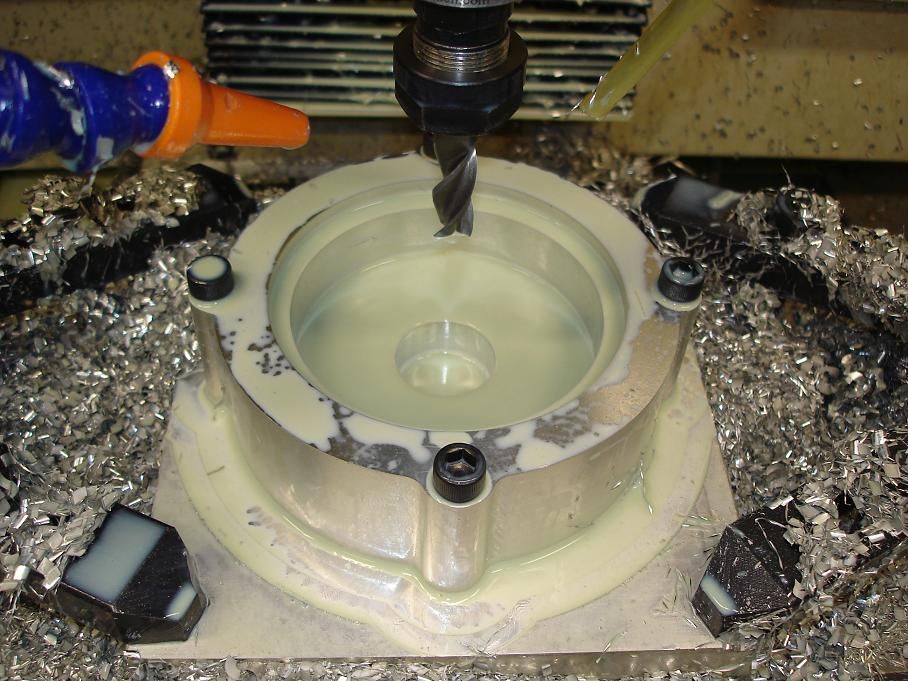
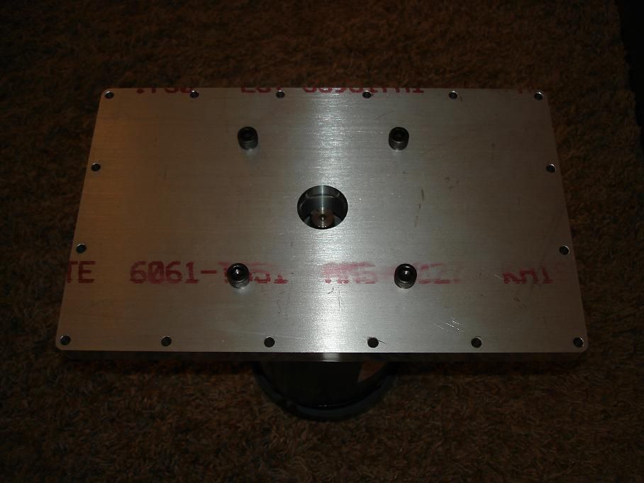
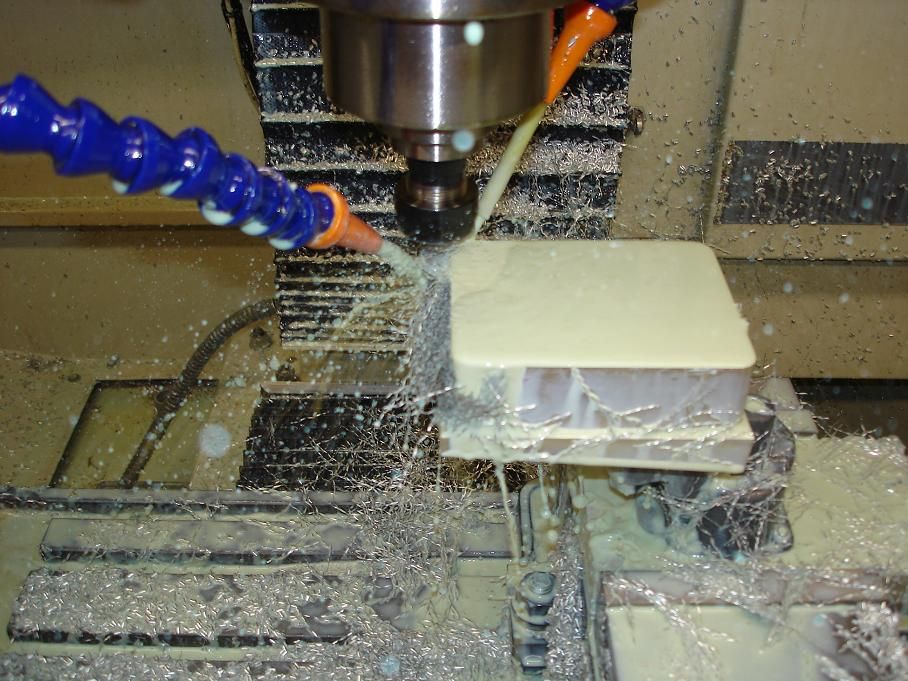
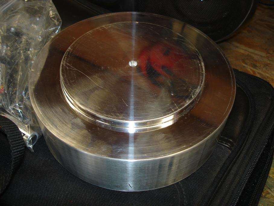
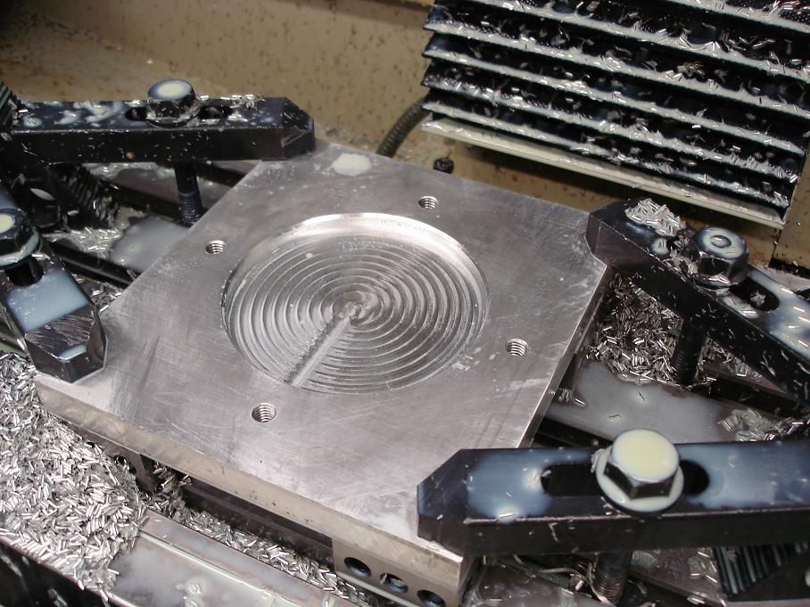
i got the motor mount done today. i fought the damn long reach endmill so the surface finish isn't quite what i was hoping for but it'll work.

the material was sawn from round stock so i chucked it up in the lathe and faced it on both sides parallel and turned a boss to center it on a plate that the pump will be mounted to.

pumpmotormount3.jpg


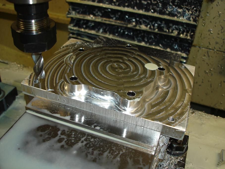
then i made a fixture to hold it in the mill.

pumpmotormount2.jpg


pumpmotormount4.jpg


pumpmotormount5.jpg


some bad shit happened while trying to fine tune the feeds and speeds for the long endmill but i'll just omit that stuff so everyone thinks i don't make mistakes
grin.gif


...<span style="font-style: italic">anyways</span>, moving on.

pumpmotormount16.jpg
 
Re: chamber flush system "build thread"

off topic but since these pictures were right here in my photobucket page, i thought i'd share.

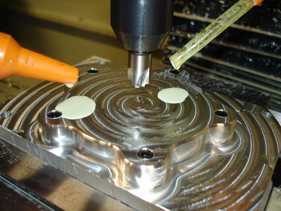
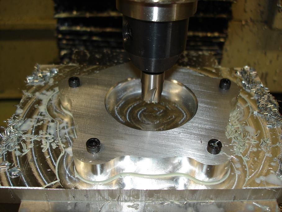
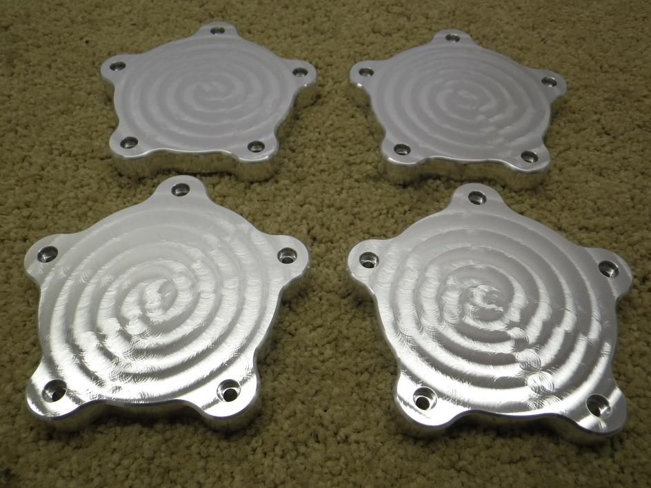
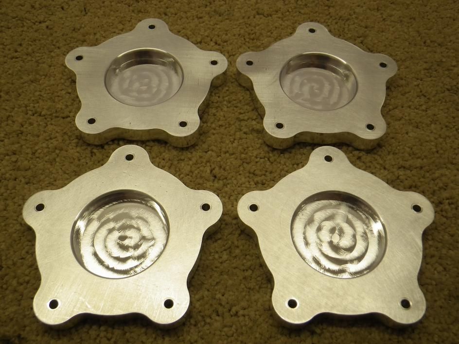
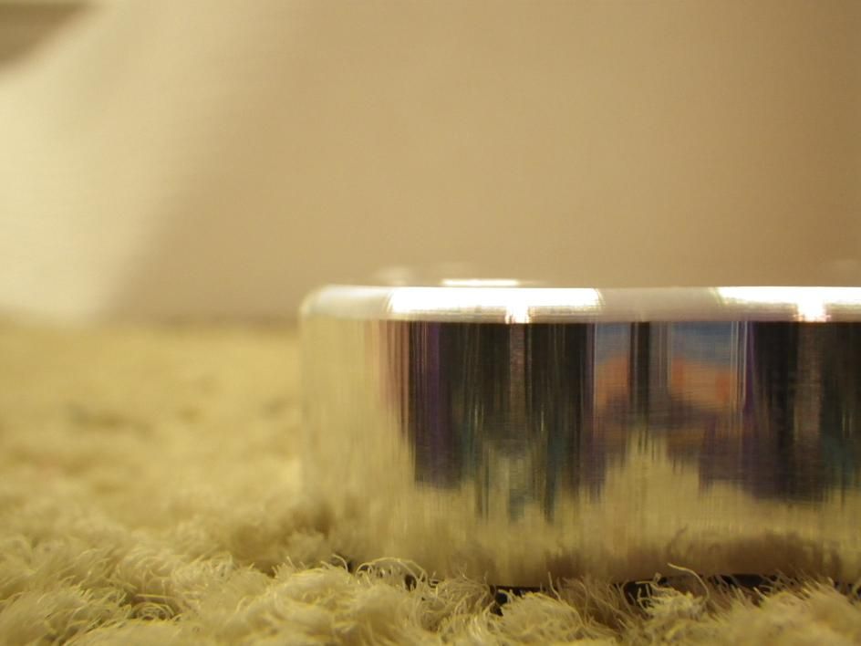
a buddy is building an old mustang for someone. they hated the cheesy cast hecho en china hub covers on the wheels. he asked if i could machine him some.

alanshubcaps27.jpg


alanshubcaps28.jpg


alanshubcovers5.jpg


alanshubcap6.jpg


alanshubcap14.jpg


alanshubcap17.jpg


he said he polished the tooling marks out but i haven't seen them finished or on the car yet. i heard that there are a bunch of guys that want them now. i may have to do a small production of them.
 
Re: chamber flush system "build thread"

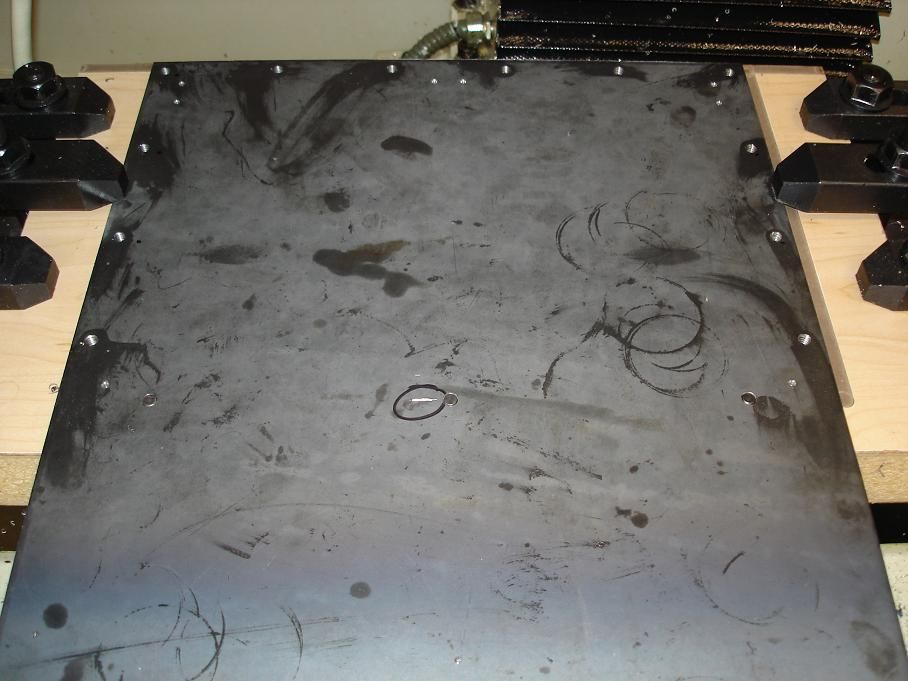
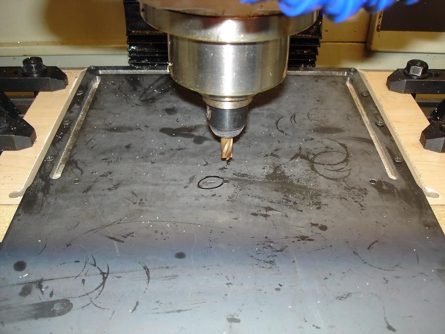
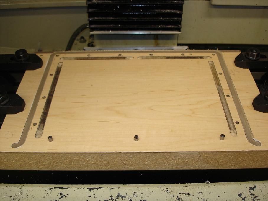
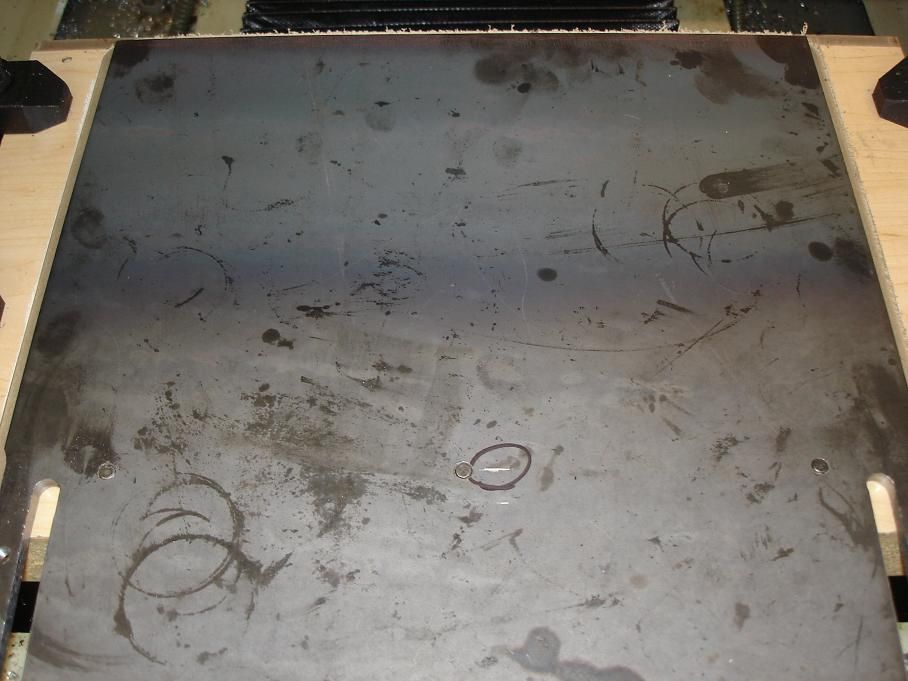
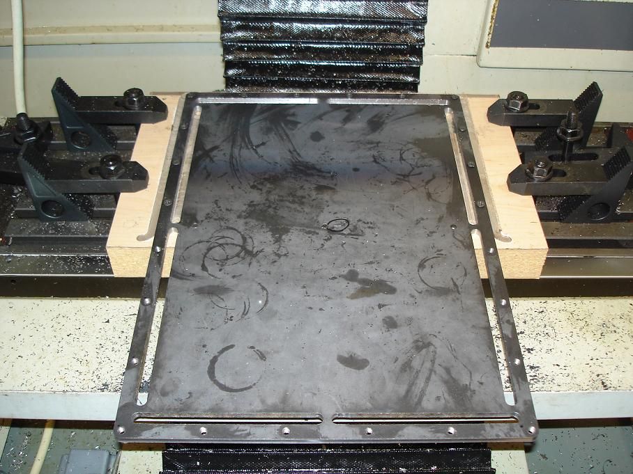
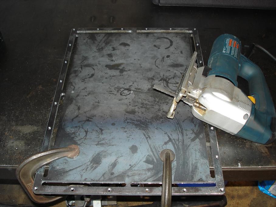
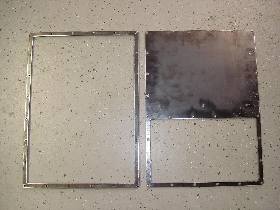
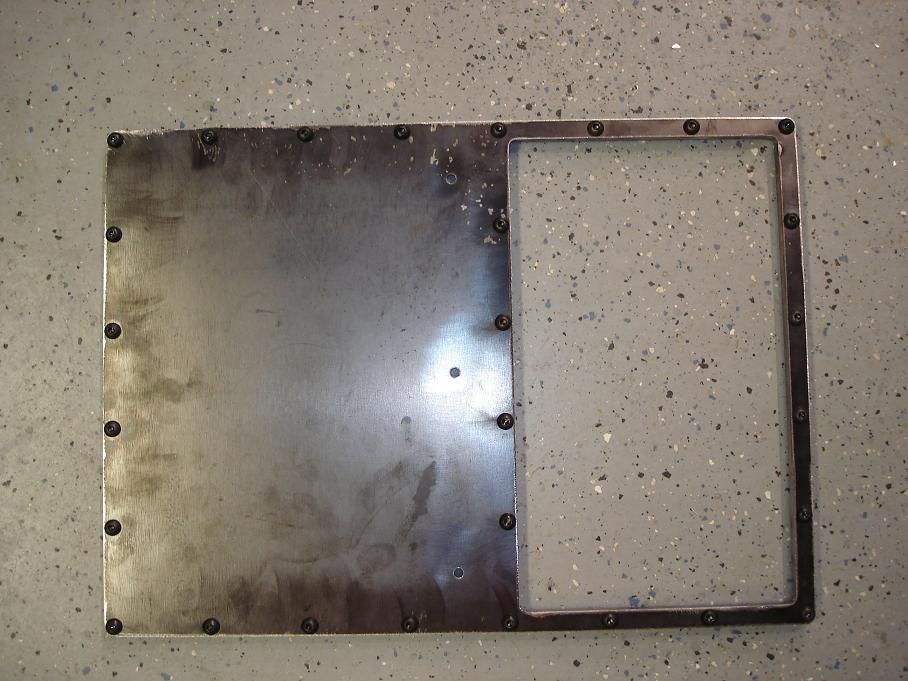
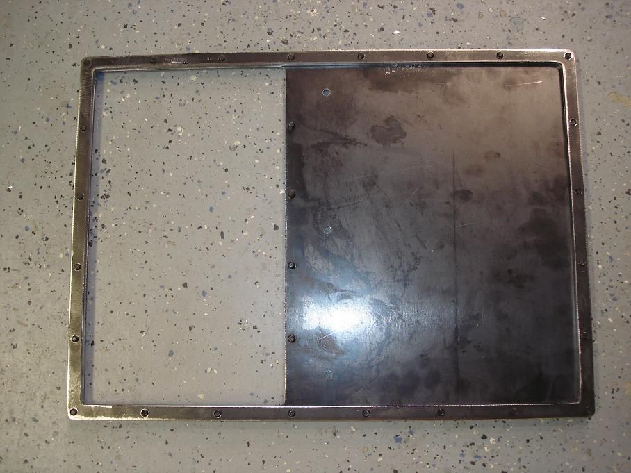
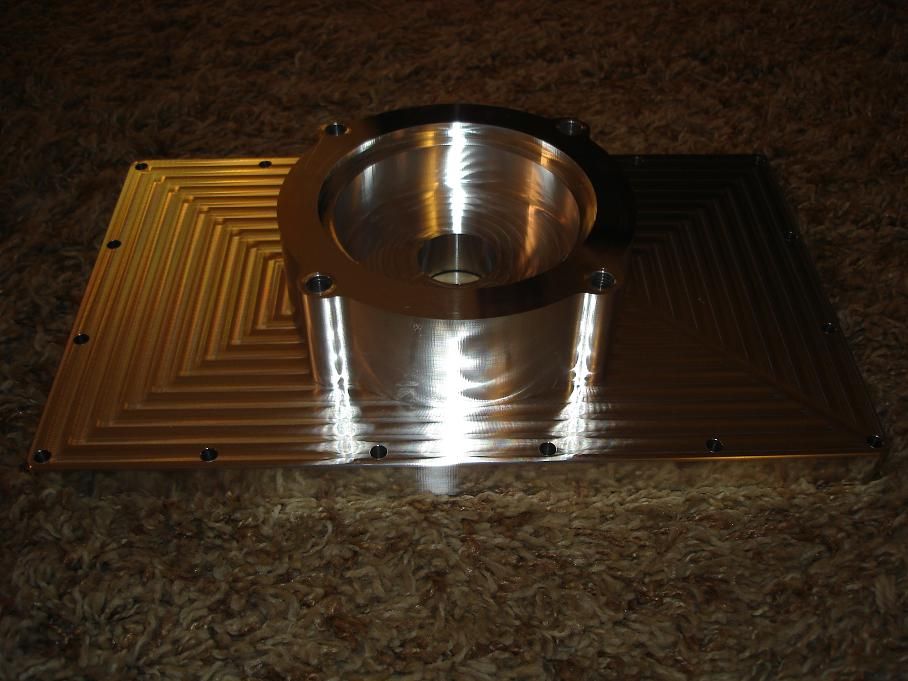
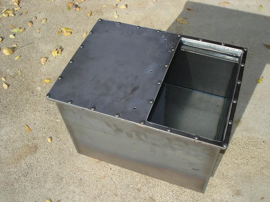
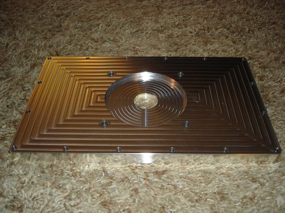
i made the flange and lid to my reservoir today. i couldn't justify the cost of having the parts waterjet so i used what i had available. it wasn't the right tool for the job nor was it big enough so i had to get creative.

making a 13" x 18" part with a machine with 18" x travel and 10" y.

flushsystemtankflangeandlid3.jpg


flushsystemtankflangeandlid7.jpg


flushsystemtankflangeandlid10.jpg


flushsystemtankflangeandlid11.jpg


flushsystemtankflangeandlid11.jpg


flushsystemtankflangeandlid15.jpg


flushsystemtankflangeandlid16.jpg


flushsystemtankflangeandlid17.jpg


flushsystemtankflangeandlid18.jpg


flushsystemtankflangeandlid19.jpg


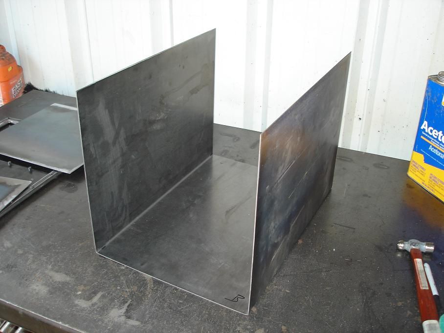
i'm going to try to bend up the box this weekend.
 
Re: chamber flush system "build thread"

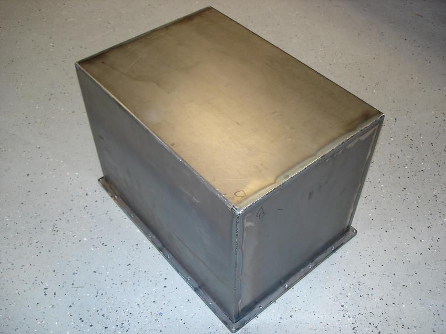
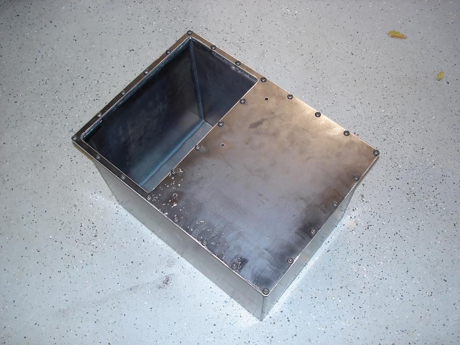
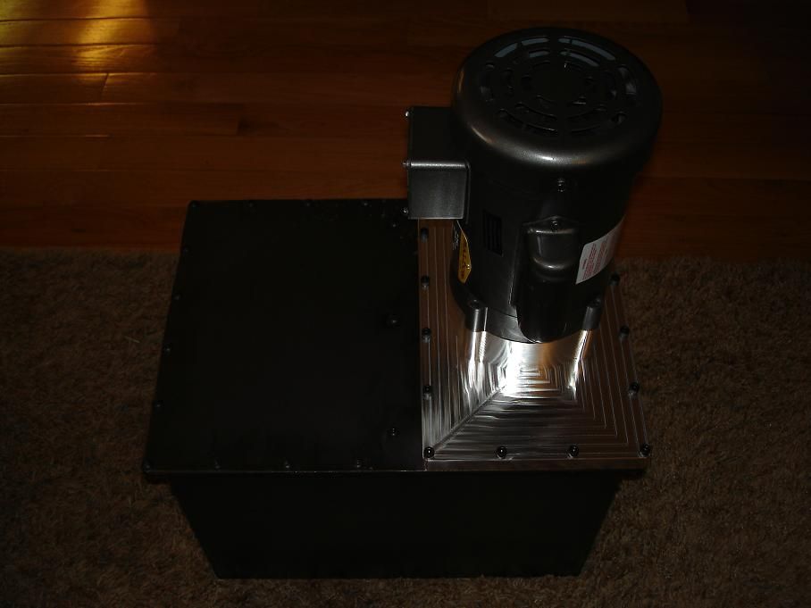
i built the reservoir this morning. it calcs out to 10.75 gallons. i figured on 10 gallons plus a bit of breathing room.

flushsystemreservoir1.jpg


flushsystemreservoir5.jpg


flushsystemreservoir6.jpg


it's been sitting for about an hour now full of water to check for leaks. i'm confident there aren't any but i better check. gravity is enough for this test but if it were for fuel on a vehicle, i'd find a way to pressurise it.

flushsystemreservoir11.jpg
 
Re: chamber flush system "build thread"

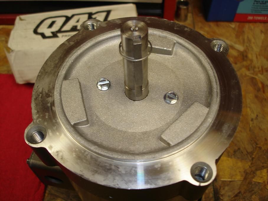
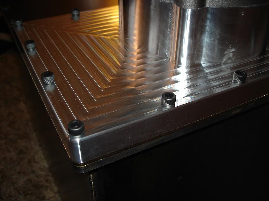
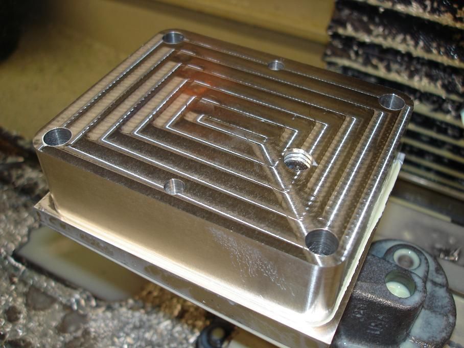
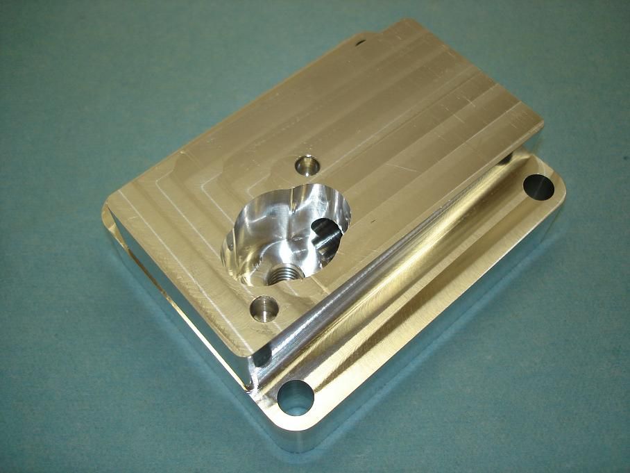
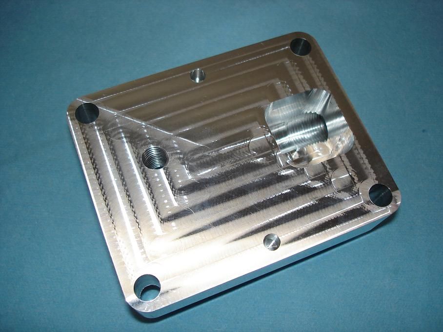
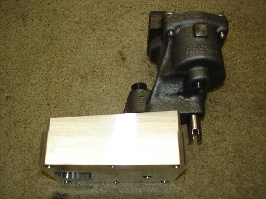
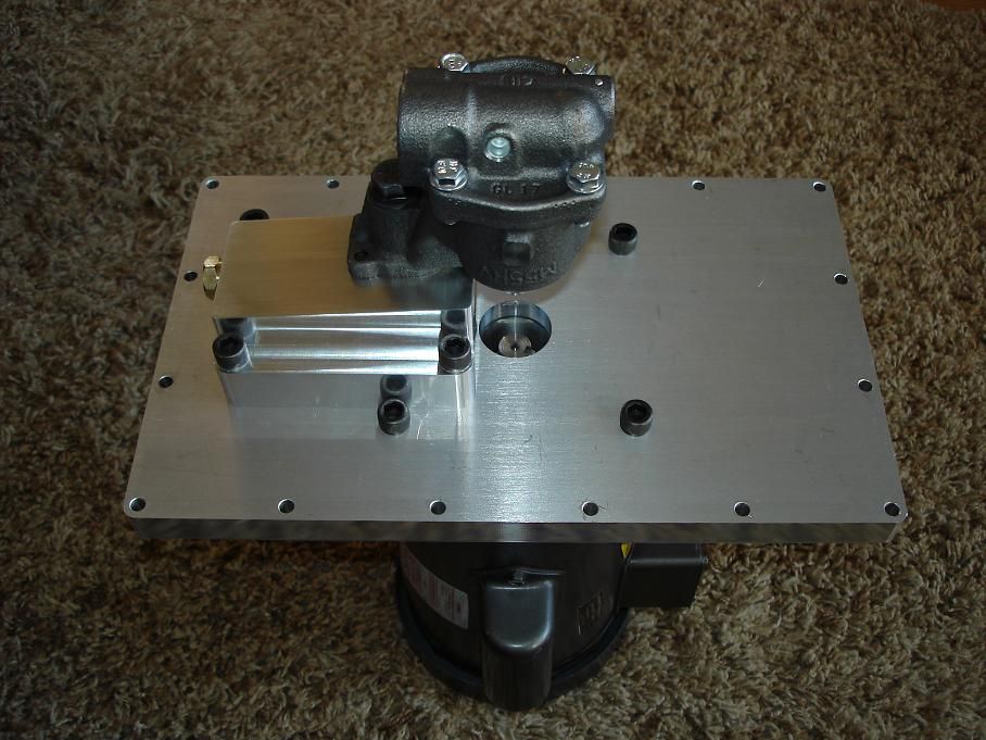
i made the pump mount today.

instead of a bunch of careful measuring and set up, i used the pump body as the holding fixture. that little pump is pretty damn rigid.

flushsystempumpmount11.jpg


flushsystempumpmount14.jpg


flushsystempumpmount18.jpg


flushsystempumpmount19.jpg


flushsystempumpmount24.jpg


flushsystempumpmount25.jpg


flushsystempumpmount26.jpg


flushsystempumpmount27.jpg


i have just a little bit more machine work to do on the motor mount plate to accept this pump mount and then i have to make the drive shaft. after that i can start plumbing it. i have a bling-bling filter drawn up but i may use a cheap off the shelf one to get this up and running for now. i have a few barrels waiting to be chambered.
 
Re: chamber flush system "build thread"

Great post 300. It's really cool to see what y'all (read highly skilled smiths/machinists) are capable of creating. I think it's gonna take a little more practice with the dremel before I can whip up a manifold and some badass motor mounts.
 
Re: chamber flush system "build thread"

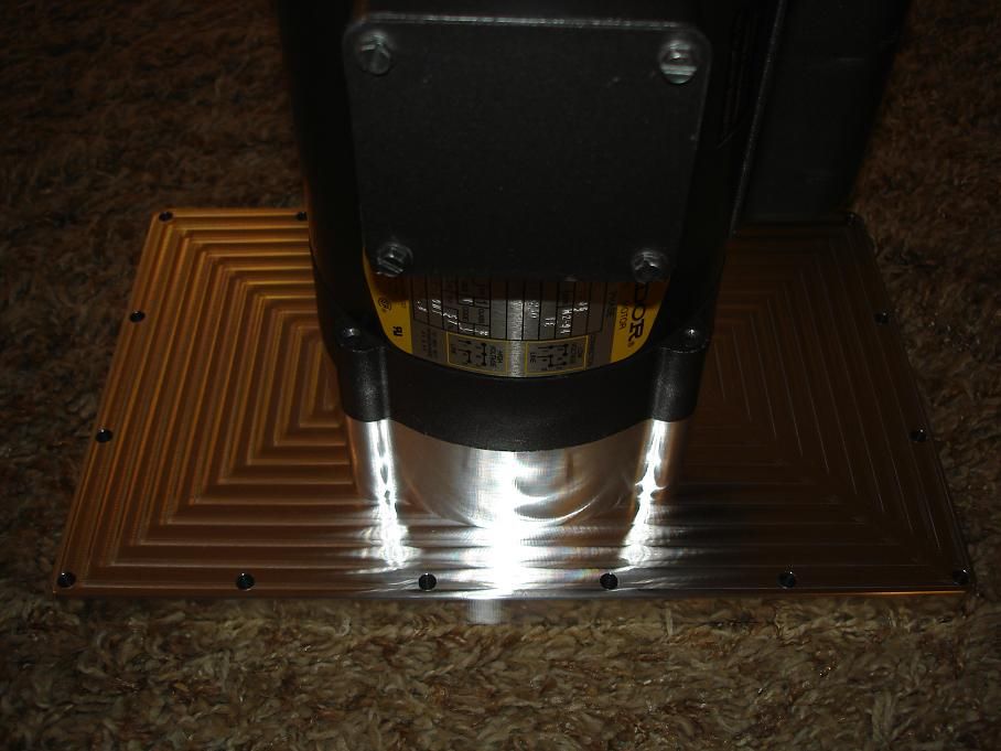
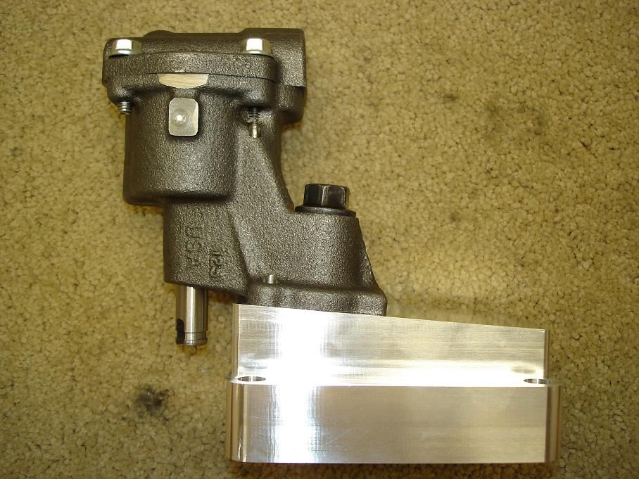
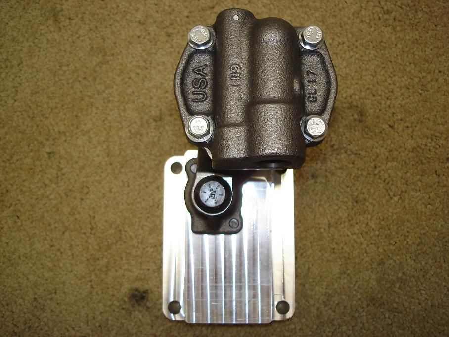
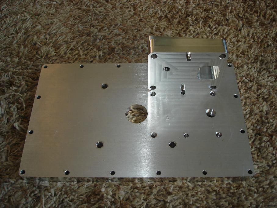
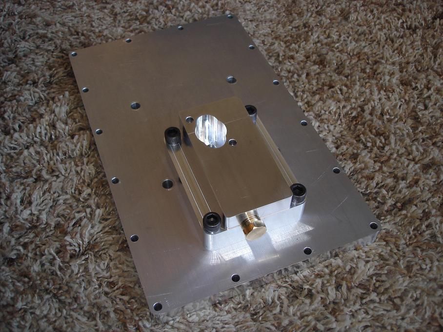
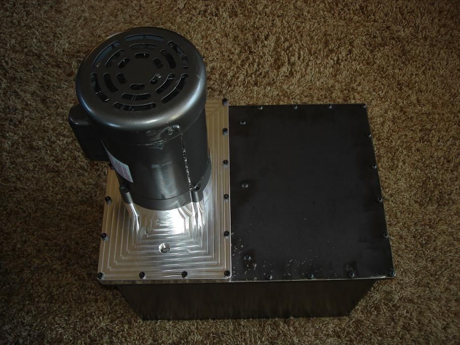
here you can see how the pump mount is doweled into the plate. everything having to do with the shaft alignment is either doweled in place or uses a boss for location. you can also see how i made the fluid passage.

flushsystemassembly2.jpg


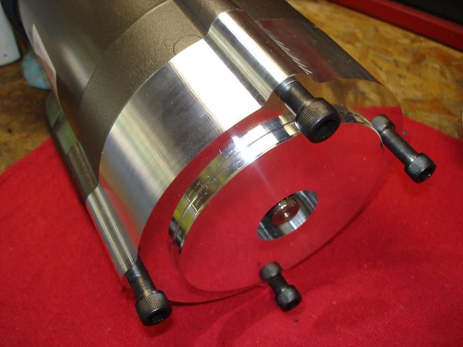
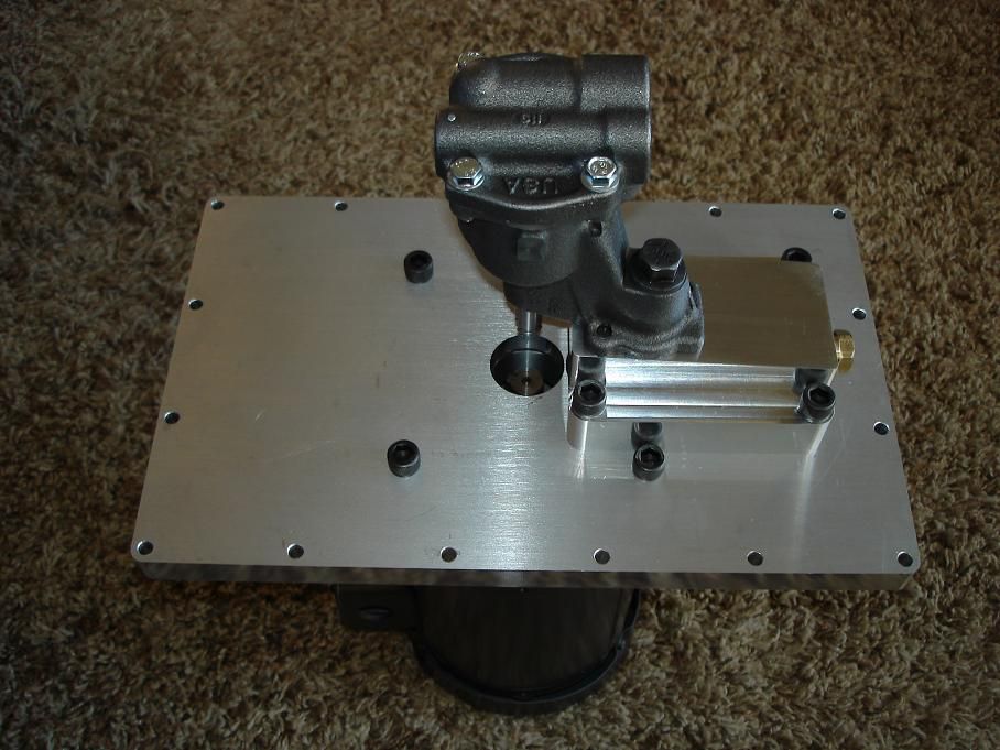
then the basic assembly.

flushsystemassembly6.jpg


flushsystemassembly7.jpg


flushsystemassembly8.jpg


flushsystemassembly9.jpg


i need to make the drive shaft and take care of the plumbing next. i also need to look at the electrical panel on my lathe to see if the coolant switch/wiring is up to the task of running this motor. if it is, i'll wire it into that using a twist lock plug. if it's not, then i'll have to come up with something else.
 
Re: chamber flush system "build thread"

<div class="ubbcode-block"><div class="ubbcode-header">Originally Posted By: 300sniper</div><div class="ubbcode-body"> I also need to look at the electrical panel on my lathe to see if the coolant switch/wiring is up to the task of running this motor. if it is, i'll wire it into that using a twist lock plug. if it's not, then i'll have to come up with something else. </div></div>

If wired for a coolant pump / coolant system it should feed through a contactor that’s controlled by the switch on the control panel. The HP rating will be the deciding factor as to whether or not it'll work with the wiring in the lathe. If it's the same or close run new wiring from the new pump to the electrical control panel and replace the old "T" leads with your new wiring leads. If the HP rating is higher on the new motor I can tell you a way to makle it work with the lathe controls and be safe atthe same time.

As long as the pump voltage is same/same as the lathe voltage you'll be gtg. If the pump is 220/240 single phase and the lathe is 220/240 3 phase your still gtg and it'll hook up the same as described above minus the third wire.

Nice clean job BTW
 
Re: chamber flush system "build thread"

<div class="ubbcode-block"><div class="ubbcode-header">Originally Posted By: X Ring Accuracy</div><div class="ubbcode-body"> but you got too much time on your hands </div></div>

this is unfortunately true these days.
 
Re: chamber flush system "build thread"

Now machine a groove in the bottom of the pump plate to cancel out cavitation. Set the gap between your rotors/plate to +.005" and you'll pick up another 5lbs of pressure without any additional drag. A slight chamfer on the rotor edges helps too along with some porting work on the delivery cavity.

I used to get stuck with blueprinting MHV55's alot when I first started working in autoracing years ago.

Cool job mister. I'm jealous.

Remember, it's not cool w/o braided lines.
smile.gif
 
Re: chamber flush system "build thread"

i'm really torn on what to do with the plumbing. part of me wants to go with earl's swivel seal npt fittings and pro-lite 350 hose but as far as i can tell, i'm going to be stuck with regular brass ball valves at the manifold. earl's has some ball valves but they don't look like something i'd want to use constantly.

i'll probably end up going with steel hydraulic fittings and keep the plumbing more "industrial" looking instead of "bling".
 
Re: chamber flush system "build thread"

<div class="ubbcode-block"><div class="ubbcode-header">Originally Posted By: AKA-Spook</div><div class="ubbcode-body">I'd bet theres a market for this if you'd ask around. Good work! </div></div>

someone would have to be pretty damn rich to afford one. in other words, i'm not making another one
grin.gif
 
Re: chamber flush system "build thread"

Robert,

I've seen numerous creative solutions to getting coolant to the bore. The most elaborate being actually turning the barrel and fitting a hose between a union.

There's an easier way. For about $300 bucks you can build this. Get a straight line hydraulic union. The one I've picked out is from Rotary Systems in Ramsey, Minnesota. (800.959.0146) PN: 007-12211

Take a piece of material, preferebly a steel HARDER than the barrel. 4140 prehard works good. Turn a center with a male 3/8NPT fitting. Drill a hole through it.

This becomes your "pressure fitting" that goes against the muzzle. Since you've not crowned it yet, there's nothing to worry about. You want the male thread on the center because this goes into the outer ring/chassis of the union. This way your not loading the seals/bearings when you put the screws to it while tightening against the bore.

NOW, build a 3 spoked deal with 3 holes out on the wings and one in the center. Center hole needs to be 1.702". Make it out of 1/2 AL plate. Cross drill and tap with 1/4-20 between the spokes towards the center hole. These become the set screws for holding the union. Drill 3/8" holes on the spoke ends.

Take some 3/8-16 all thread and chop it up into 3 equal length segments. Build 3 washers around 3/8" thick and tap the centers to 3/8-16. Screw them flush with the end of the all thread. Tac with a Tig or sweat some solder in them. Just don't want them coming off.

Now build a plate with 3 CAM lock features that'll attach to the back of your lathe. You make three holes slightly larger than the washers and machine a groove on the back side with a detent for them to fall into.

Setup your barrel as normal. Then slide the assembly into the cam locks. Twist and lock into place. With three previously made thumb screws start tightening up the all thread. It'll pull against the back plate and apply pressure at the center.

With you plumbing already installed on the opposite end of the union your ready to chamber.

It's really that easy. No machining to the barrel required. We chambered 5-15 barrels a day exactly like this at Nesika. I used anywhere from 200-600lbs of oil pressure. I pressure tested the entire thing to over 1000psi. They still use this same setup today and I built it in 2004. It works.

Never a drip.

The barrel and center rotate together, so there's never any wear. There's no load on the AN fitting/braided hose so it lasts forever too.

Rig a pair of system one oil filters in series and you'll save the carbide/teflon seals in the union. As the photo shows, this is the one area that I underestimated and it bit my ass. Christmas day, 2005 I was chambering my palma gun. The System One filter enclosure failed and about a gallon of oil shot all over the shop ceiling, walls, floor, etc. Was a real mess. The pressure from the pump (Rem Cool 2400) split the thin wall cast AL wall of the system one setup. I built two new enclosures and used the reusable screen elements in the filters. 4140 caps on both ends to seal it up. Never leaked again after that. Since your using a MHV55 pump you'll never get to the pressures I was monkeying around with. The factory system one setup should work fine. Trans Dapt makes a cheap (affordable) cast dual remote filter setup that'll work great for this. Runs around $40 bucks and any hot rod oriented parts shop will likely have them.

It's quick, simple, and dead nuts reliable.

The drip pan under this was for when pulling it off. Oil drains into the pan and back to the sump via a hose. I had an HVAC shop bend it up for me because we didn't have a brake for sheet metal at Dakota when I built this. A guy could probably modify a big cake pan from a bakery supply place to work pretty easily.

The long rod on top with the two flat on it were for attaching the indicator to line up the barrel. Just a simple way to clamp the indicator. Worked well for how we did it back then.

Good luck.

PS: Its a rare day that I see someone put as much effort/thought into something as you have demonstrated here today. Well done and I hope it works awesome for you. Hats off and cheers.
Quickreleasecoupler.jpg


Hydraulicunion.jpg


Filters.jpg
 
Re: chamber flush system "build thread"

Yalls posts always make me think, always impressed with your ingenuity, always admire the quality of the finished products. Thanks for once again making me feel like a no talent ass clown!
 
Re: chamber flush system "build thread"

a couple people have asked about this recently but unfortunately i don't have any updates. my sheet metal buddy moved out of state so i either have to cut and weld all the pieces to make a new chip pan/screen/sump or pay someone to bend it up for me. i don't feel cutting and welding all the pieces is the right way to do it so i'll probably end up paying someone to bend it. when i eventually make the new chip pan, i want to have it and the reservoir powder coated. my day job has pretty much sucked for the last few months so spending money on stuff that doesn't make me money has been put on hold for a while, including this project.
 
Re: chamber flush system "build thread"

300 i tried to PM you but you're over your limit. Do you have a print for what you want bent up? I might be able to help you out free of charge (other than shipping). Powder coating could be an option too as long as you want it in white. I work in a Weld shop with both heavy fab and sheet metal divisions. Plenty of time for gov't work on saturdays and we have plenty of brake presses.
 
Re: chamber flush system "build thread"

<div class="ubbcode-block"><div class="ubbcode-header">Originally Posted By: propeine</div><div class="ubbcode-body">300 i tried to PM you but you're over your limit. Do you have a print for what you want bent up? I might be able to help you out free of charge (other than shipping). Powder coating could be an option too as long as you want it in white. I work in a Weld shop with both heavy fab and sheet metal divisions. Plenty of time for gov't work on saturdays and we have plenty of brake presses. </div></div>

Heck of a first post.

Welcome.
 
Re: chamber flush system "build thread"

Haha thank you. I guess I could have introduced myself first. Times are tough on a lot of people and 300 has posted all of his builds which I have read so if I can give back I'm sure as hell gonna try.

I am not as knowledgeable on machining, although I just bought a lathe, or on lots of long range shooting or on optics, or all kinds of other things so I spend my time reading more than posting. But I'm a project manager at a weld shop, a pretty damn good welder myself, went to school for mechanical engineering and determined to learn everything I can. I guess I can mention that I'm a country boy that got his first 22 at 10 years old so I'm a decent shot but nowhere near some of you guys ability.
 
Re: chamber flush system "build thread"

wow that is really impressive! you sent a lot of time making your pump and getting it working. excellent work. how much time did it save on a chambering job? did it keep all the chips flushed out or do you still have to bring the reamer out every 100 thou or so to clean the chips out?
 
Re: chamber flush system "build thread"

<div class="ubbcode-block"><div class="ubbcode-header">Originally Posted By: propeine</div><div class="ubbcode-body">300 i tried to PM you but you're over your limit. Do you have a print for what you want bent up? I might be able to help you out free of charge (other than shipping). Powder coating could be an option too as long as you want it in white. I work in a Weld shop with both heavy fab and sheet metal divisions. Plenty of time for gov't work on saturdays and we have plenty of brake presses. </div></div>

that's a hell of an offer. thank you.

i still need to design and draw up the chip pan. once i get it figured out, if i can't find a local shop to help me out, i'll get in touch with you. 'cept i don't think white powdercoat will be fung shui with my setup
grin.gif
 
Re: chamber flush system "build thread"

<div class="ubbcode-block"><div class="ubbcode-header">Originally Posted By: 300sniper</div><div class="ubbcode-body">
'cept i don't think white powdercoat will be fung shui with my setup
grin.gif
</div></div>

You never know. A little gold trim and it'll look pimptastic!
laugh.gif
 
Re: chamber flush system "build thread"

Translucent candy apple red over a gold undercoat w/ some flake in it? All kidding aside I can get many more colors but its $150 setup fee to change colors that I can't work around unless you wait for the very rare times that they change to black or grey.