Join the Hide community
Get access to live stream, lessons, the post exchange, and chat with other snipers.
Register
Download Gravity Ballistics
Get help to accurately calculate and scope your sniper rifle using real shooting data.

Install the app
How to install the app on iOS
Follow along with the video below to see how to install our site as a web app on your home screen.
Note: This feature may not be available in some browsers.
You are using an out of date browser. It may not display this or other websites correctly.
You should upgrade or use an alternative browser.
You should upgrade or use an alternative browser.
Homemade Induction Annealer
- Thread starter TSloper
- Start date
Heck ya! I’m so tempted to build one!I have almost every part to put one together.
Just started writing the code to run it.
The idea and possible results are pretty cool.Heck ya! I’m so tempted to build one!
Thank you very much The_Steward
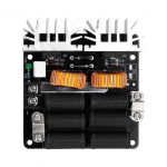
In fact, after reading the various posts I decided to focus on one of these 2 (photos attached)
One has 6 capacitors of 0.3, the other has 7
Both with cooling fans for the circuit.
One question is this, can I start from the terminals of the circuit with an electric wire and then get to the empty tube of the spiral?
Or does the tube have to be anchored to the clamps marked in the photo?
Otherwise it is impossible for me to pass the liquid inside the tube given how this circuit is made.
Or the smaller one with 6 capacitors which is easier having the free terminals behind.
I should also understand how to do the calculations described in your video of post n° 637.
Because being in English I missed some quite fundamental steps to calculate the coils
is it possible to have the excel table you show in the video?
I don't have the excel file unfortunately, I just built it on the fly for that video.
For the wiring, yeah, you can use leads to the coil. Make sure you use heavy stranded wire for it. Maybe 10 gauge, but 1/4" copper tubing has roughly the same cross sectional copper area as 5 gauge wire, for reference. So, you want to keep an eye on the leads to see if they are getting too hot, and if they are, you might need to swap in larger leads. It just depends on the power you're running.
If anyone needs a power supply for one of these just DM me. I picked up several from my work when they upgraded computer systems. They are Meanwell 24vdc 56amp/ 1500 watt units. Used, but tested and in great shape. It's way oversized but cheap for Hide members. I made a hotwire foam cutter with one. And I guess I'm procrastinating on making my own annealer. Ill be kicking myself come spring when the weather is nice and I'm in the basement soldering.
Edited: corrected max wattage from 3000 to 1500.
Edited: corrected max wattage from 3000 to 1500.
Last edited:
It sure in interesting tech. I don't have something like this but I do have one for rusty bolts and nuts on cars and such. The thing is just flat amazing. One of those tools you say, where have you been all my life......but.
When trying to get bolts out of an old leaf spring setup and you think of that cool new induction heater think again, those rubber mounts will smoke like hell, and keep smelling bad for days after. Ask me how I know.
It seems that this would be so much better then the propane deals I had been looking at.
Hi, I was really thinking about starting to put the pieces together for the Induction Annealer machine.
Can you confirm that this card (I put the photo below) with 6 capacitors and a 48v 600w power supply can heat the shell to make the machine work?
Also after watching various videos I wanted to make the coil with the 4mm external diameter tube (3mm internal diameter) and continue with the 5mm external (4mm internal) to get to the cooling system. Are the diameters of the pipes correct?
Using our professor The_Steward's beautiful salt technique.
I hope I explained myself well and above all guess the number of turns to do since my spoken and listened English is not very good.
Thanks a lot everyone
Attachments
Is that 240v input?If anyone needs a power supply for one of these just DM me. I picked up several from my work when they upgraded computer systems. They are Meanwell 24vdc 56amp/ 3000watt units. Used, but tested and in great shape. It's way oversized but cheap for Hide members. I made a hotwire foam cutter with one. And I guess I'm procrastinating on making my own annealer. Ill be kicking myself come spring when the weather is nice and I'm in the basement soldering.
It sure in interesting tech. I don't have something like this but I do have one for rusty bolts and nuts on cars and such. The thing is just flat amazing. One of those tools you say, where have you been all my life......but.
When trying to get bolts out of an old leaf spring setup and you think of that cool new induction heater think again, those rubber mounts will smoke like hell, and keep smelling bad for days after. Ask me how I know.
It seems that this would be so much better then the propane deals I had been looking at.
It'll do ok, just make sure to monitor the temps on the MOSFETs and capacitors if you're running it very long.
Hmm... it'd have to be a custom110v circuit. Max you can get from standard outlets is 1800w.It's 110-220vac input.
Also, for a 24v output, it'd be cranking 125A to hit 3kw. That's a beefy boi.
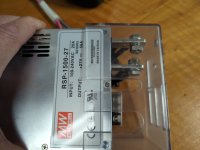
Still, 1500w is a beefcake. Look at those lugs!It is. But you are right, it is only a 1500watt power supply. Still, 56amps at 24vdc is pretty good. I'll have to edit my prior post. I must be getting old to have made that mistake.
Hi,
I've been a long road of building ma MGNZ annealer like most of us.
Right now, Im encountering the following problem.
When I install a new 7,5 turn coil with the 6mm copper tubes soldered to them, the machine runs perfectly for about 30 to 40 cases of 308 at about 5 secs to make them glowing.
The problem is after that amount of cases the tempreture will not be as high to get it near to glowing any more even if I turn up the annealing time by 2 secs.
Anybody ever had the same problem? What is the solution for this?
Thanks!
Can you keep the temperature of the mosfets under control?
I would not like the increase in temperature to make the circuit work worse.
I would not like the increase in temperature to make the circuit work worse.
Can you keep the temperature of the mosfets under control?Hi,
I've been a long road of building ma MGNZ annealer like most of us.
Right now, Im encountering the following problem.
When I install a new 7,5 turn coil with the 6mm copper tubes soldered to them, the machine runs perfectly for about 30 to 40 cases of 308 at about 5 secs to make them glowing.
The problem is after that amount of cases the tempreture will not be as high to get it near to glowing any more even if I turn up the annealing time by 2 secs.
Anybody ever had the same problem? What is the solution for this?
Thanks!
I would not like the increase in temperature to make the circuit work worse.
Hi,Can you keep the temperature of the mosfets under control?
I would not like the increase in temperature to make the circuit work worse.
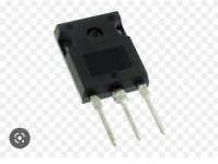
Im sorry, I cant find a translation for "mosfets"; which part is it?
One thing I forgot to mention is that the annealing tempreture cannot be reached any more even if I let everything cool down over night.
I also removed the coil and made the contact surfaces clean with sandpaper. This did not solve my problem...
Hi,
I've been a long road of building ma MGNZ annealer like most of us.
Right now, Im encountering the following problem.
When I install a new 7,5 turn coil with the 6mm copper tubes soldered to them, the machine runs perfectly for about 30 to 40 cases of 308 at about 5 secs to make them glowing.
The problem is after that amount of cases the tempreture will not be as high to get it near to glowing any more even if I turn up the annealing time by 2 secs.
Anybody ever had the same problem? What is the solution for this?
Thanks!
Could be several things. First, after long periods of use, stuff gets hot, and resistance in the ZVS circuit goes up. Second, your power supply can also start to sag a bit when it gets hot after long use at full power as most PSUs have derated power at higher temps.
From your follow up post, it sounds like you toasted your ZVS circuit.
Interesting thing is I had the same problem before and I made a new coil.
The new coil worked fine for about 50 cases, than the same problem appeared...
Hi,
Im sorry, I cant find a translation for "mosfets"; which part is it?
One thing I forgot to mention is that the annealing tempreture cannot be reached any more even if I let everything cool down over night.
I also removed the coil and made the contact surfaces clean with sandpaper. This did not solve my problem...
These here where the heat sinks are
Attachments
So, since a couple of people here and elsewhere have asked me about the work coil, and how many turns they should use, etc... I have made a video that covers how to determine what your work coil needs to be. You have to take into account several factors, but I've simplified it for the direct application to these types of heaters. You want to shoot for something that resonates in your circuit somewhere between 75khz-150khz. Using your capacitor bank and the resonant frequency formula, you can then set a range for the inductance you need. With this and the size of brass you want to be able to anneal, you can then use a coil calculator to figure out how many turns your coil needs. Power and heat generated will also factor into the coil size, since you'll want to use 3/16 or 1/4 inch copper tubing, and that will impact the inductance of your coil.
The calculator will give you a ballpark estimate of the inductance of a coil based on its size and number of layers/turns. At that point, you'll have the design laid out. You'll need to get a core with the right dimensions for winding, and then just wind the correct number of turns/layers. I am going to make a second video where I demonstrate a fairly reliable method to make a good coil without collapsing the tubing. I'll probably have that up in a day or two. The trick is to use regular table salt with good crimped ends, and then use a fitting adapter on a hose bib on your house. It'll dissolve and push the salt out pretty quickly. Ice, sand, and the other methods I've tried haven't been nearly as easy, quick, or reliable.
Hi guys, hi the_Stewaer (I also wrote to you on YouTube that I finished making the coil)
I'm in trouble.
I just finished assembling the whole circuit.
I made a video tomorrow I'll put it down here now it won't let me put it on my phone…
Forgive my spoken English which is awful

Anyway summarizing: adjust the power supply to 42.5 v the card turns on, but as I put something inside it goes into protection. If I put it higher at 48 v it goes into protection immediately.

I followed the video for the calculations and the one for how to make the coil with 1/4 tube
This is the ZVS card (I took it on aliexpress but it is the same) 6 condensators of 0.30 uF
Amazon product ASIN B0B37F1Y7H
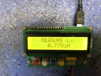
Measuring with the video tool 0.544 uH and following the table from a frequency that is in our working range 118.785 KHz.
The power supply acts from a minimum of 42.5v to a maximum of 53 (I stopped at 48V, as per the card indications) for 600W.
I don't understand where the problem is
Help me please
Attachments
Hi guys, hi the_Stewaer (I also wrote to you on YouTube that I finished making the coil)
I'm in trouble.
I just finished assembling the whole circuit.
I made a video tomorrow I'll put it down here now it won't let me put it on my phone…
Forgive my spoken English which is awful
Anyway summarizing: adjust the power supply to 42.5 v the card turns on, but as I put something inside it goes into protection. If I put it higher at 48 v it goes into protection immediately.
I followed the video for the calculations and the one for how to make the coil with 1/4 tube
This is the ZVS card (I took it on aliexpress but it is the same) 6 condensators of 0.30 uF
Amazon product ASIN B0B37F1Y7H
Measuring with the video tool 0.544 uH and following the table from a frequency that is in our working range 118.785 KHz.
The power supply acts from a minimum of 42.5v to a maximum of 53 (I stopped at 48V, as per the card indications) for 600W.
I don't understand where the problem is
Help me please
I would suspect that the coil is too small. The circuit probably ends up with total impedance that's too low, and draws too much current. Do you have a current meter on the power to see what it's drawing?
I could only measure the current on the primary and it is really high…I would suspect that the coil is too small. The circuit probably ends up with total impedance that's too low, and draws too much current. Do you have a current meter on the power to see what it's drawing?
At 230v of 4.31A (990w) with no material inside the coil.
Making an approximate calculation on the secondary I have about 20A.
In fact, as soon as the load increases, the power supply goes into protection.
How can I fix it? Do you have a solution?
I could only measure the current on the primary and it is really high…
At 230v of 4.31A (990w) with no material inside the coil.
Making an approximate calculation on the secondary I have about 20A.
In fact, as soon as the load increases, the power supply goes into protection.
How can I fix it? Do you have a solution?
I can only guess. But as I said, the coil you made is probably too small (low inductance). Try making a coil with higher inductance.
Can you verify everything works with the stock coil that the ZVS came with?
Thank you very much you are very kind.I can only guess. But as I said, the coil you made is probably too small (low inductance). Try making a coil with higher inductance.
Can you verify everything works with the stock coil that the ZVS came with?
No, I can not.
I took the electric card without coil, because its original one is 40 mm wide.
Do you have an idea how much inductance it should have?
So I try to make it with that inductance
I'm not understanding anything anymore.
I increased the inner diameter by 4mm.
Now the coil is: internal diameter 20.7 mm
external diameter 45 mm
high 40mm
I increased the number of turns of the coil up to 0.778uF.
But it always does the same thing: it just runs on idle. As soon as I put anything in it stops.
At 42.5 v DC it is always very high as no-load current, about 14A

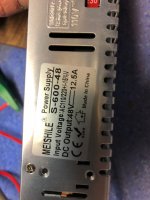
Isn't the problem that it says 1000w ZVS and the PSU is only 600w? Shouldn't that work the same?
I increased the inner diameter by 4mm.
Now the coil is: internal diameter 20.7 mm
external diameter 45 mm
high 40mm
I increased the number of turns of the coil up to 0.778uF.
But it always does the same thing: it just runs on idle. As soon as I put anything in it stops.
At 42.5 v DC it is always very high as no-load current, about 14A
Isn't the problem that it says 1000w ZVS and the PSU is only 600w? Shouldn't that work the same?
Attachments
Last edited:
Based on the picture of your power supply, it is only rated for 12.5 amps. May not be enough.I'm not understanding anything anymore.
I increased the inner diameter by 4mm.
Now the coil is: internal diameter 20.7 mm
external diameter 45 mm
high 40mm
I increased the number of turns of the coil up to 0.778uF.
But it always does the same thing: it just runs on idle. As soon as I put anything in it stops.
At 42.5 v DC it is always very high as no-load current, about 14A
Isn't the problem that it says 1000w ZVS and the PSU is only 600w? Shouldn't that work the same?
I only base that on the current draw that my 1000W/48V ZVS board pulls. When I was using a 1000W/48V/21A power supply, it was about 14-17 amps, now I am using a 1500W/48V/31A power supply and it pulls 22-23 amps.
Also, make sure that your coil is not shorting somewhere (use a piece of thread/string and run it between the coils from end to end to find any tight spots where the coils may be touching).
No no the coil is ok.Based on the picture of your power supply, it is only rated for 12.5 amps. May not be enough.
I only base that on the current draw that my 1000W/48V ZVS board pulls. When I was using a 1000W/48V/21A power supply, it was about 14-17 amps, now I am using a 1500W/48V/31A power supply and it pulls 22-23 amps.
Also, make sure that your coil is not shorting somewhere (use a piece of thread/string and run it between the coils from end to end to find any tight spots where the coils may be touching).
It doesn't touch anywhere.
The problem at this point is the power supply.
I have to get at least a 1200w
Here are the primary components...
ZVS Board ($36.62) - Amazon product ASIN B01C70G7Y8
5-36V Timer/Relay Board ($12.99) - Amazon product ASIN B07V24WJ4S
24V/15A Power Supply ($21.99) - Amazon product ASIN B0196PXMTU
Momentary Switch ($8.99) - Amazon product ASIN B06XSBYNM7
750F Tempilaq ($30.49) - Amazon product ASIN B00PL7SEUU
Copper Wire ($17.87) - https://www.lowes.com/pd/Southwire-25-ft-8-Gauge-Soft-drawn-Copper-Bare-Wire-By-the-Roll/50372842
Cord for power supply - Lowes carries a wall plug cord that is has the L/N/GND wires exposed. Just go to where they sell extension cords and you will find it.
Feel free to ask questions. The coil winding is key. My coil is 10 turns with an ID of 15-16mm. I wouldn't go more than 20mm if you adhere to the setup above. If you aren't sure your coil dimensions/turns will work message me and I can tell you if it will work acceptably. I will need to know coil wire diameter, coil turns, and ID. The opening of the case mouth is positioned to be right about mid way in the coil.
Other timer boards can be used but make sure it supports the voltage/current needs. The timer board I used is using two N-channel FETs in parallel rather than traditional relays. It is working very well. Other ZVS boards can be used as well but you will have to take note of how much capacitance the board has when deciding the coil specs. I'm an EE btw so this project was right up my alley.
Quick tip on turning the coil with that particular wire... use a wooden dowel or similar and turn the coil as tight as possible. Once it is turned take 5-6 business cards and slide them through the coil windings. This will then give you uniform spacing between the coils. Just make sure none of the coils touch and you will be fine. At the mounting ends of the coil I just soldered the 8 AWG wire into the center of a couple pieces of 1/4" copper tubing. This allowed the coil to mount as intended with this particular ZVS board.
If you opt to mimic the wooden block approach the proper drill bit size for 223 is 13/32". You want just enough clearance that the case will drop freely but not tilt excessively. I made the base board hole under that 1/2". Everyone will have their own approaches but just make sure you dimension the case support such that the case mouth opening is about mid way in the coil.
Tim
In this list of yours you used the same ZVS that I took but a 24V 15A power supply, which would be 360w.
Did your circuit work?
I don't understand why mine has to go up so much ampere
Something to consider (let smarter people chime in before deciding), I have read that you can run 2 power supplies in series to increase the output voltage, but can you run 2 supplies in parallel to increase your amperage?
I only mention this, because it may be cheaper to get another 48V/600W supply to double your amperage to 25A using the supply you have and another just like it...
I'm actually very curious if this could work...
I only mention this, because it may be cheaper to get another 48V/600W supply to double your amperage to 25A using the supply you have and another just like it...
I'm actually very curious if this could work...
you are actually right, but why risk it when most likely on Aliexpress I can get a 1200W and give it back?Something to consider (let smarter people chime in before deciding), I have read that you can run 2 power supplies in series to increase the output voltage, but can you run 2 supplies in parallel to increase your amperage?
I only mention this, because it may be cheaper to get another 48V/600W supply to double your amperage to 25A using the supply you have and another just like it...
I'm actually very curious if this could work...
you are actually right, but why risk it when most likely on Aliexpress I can get a 1200W and give it back?
Yeah, overall, it's just hard to know without verified "good" components to test with. It could be a fault in the ZVS circuit, it could be a problem with the PSU, or it could be a problem with the coil.
I just checked the stock coil I have. It's about 0.85uH (6.5turns, 42.5mm ID), although my little LCR meter isn't always very consistent, so don't put too much faith in that number.
Hello guys,
It seems that he has reached an acceptable compromise for now.
Increased the internal coil diameter to 29mm. (3 rounds x 2)
The annealing times are increased to about 11 seconds but at least it works and the power supply manages not to go into protection.
It can't heat a full iron of diameter 6 but it's fine for the shell.
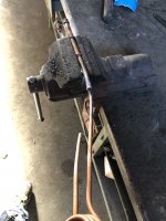
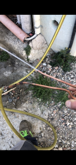
I also solved the problem of the fitting for the tube to be attached to the water tap to let the salt out by welding tubes of always higher diameter to be able to insert it directly into the water tube and put a normal iron clamp to tighten.
Later I will try to replace the power supply with a 25A one
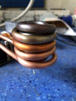
In the first picture I had just unsoldered the spiral from all the tubes
Thanks to everyone for the precious advices.
It seems that he has reached an acceptable compromise for now.
Increased the internal coil diameter to 29mm. (3 rounds x 2)
The annealing times are increased to about 11 seconds but at least it works and the power supply manages not to go into protection.
It can't heat a full iron of diameter 6 but it's fine for the shell.
I also solved the problem of the fitting for the tube to be attached to the water tap to let the salt out by welding tubes of always higher diameter to be able to insert it directly into the water tube and put a normal iron clamp to tighten.
Later I will try to replace the power supply with a 25A one
In the first picture I had just unsoldered the spiral from all the tubes
Thanks to everyone for the precious advices.
Attachments
My setup:
1000w zvs board with six .33microf caps
12v power supply
SSR
36v 16.6 a power supply set to 35v
2 layer coil, 4.25 turns per layer, 3/4" ID on the inner layer, using the common 1/4" tubing
coolant with fan and radiator
For a faint glow in dark room:
3.7s for 6.5 creedmoor
4s for 6GT
1000w zvs board with six .33microf caps
12v power supply
SSR
36v 16.6 a power supply set to 35v
2 layer coil, 4.25 turns per layer, 3/4" ID on the inner layer, using the common 1/4" tubing
coolant with fan and radiator
For a faint glow in dark room:
3.7s for 6.5 creedmoor
4s for 6GT
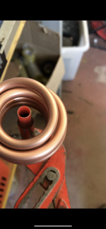
HaHa - it works So ugly and it drips a bit when running but it anneals a .308 LC brass in 4.5 seconds and the copper tube stays cool


So ugly and it drips a bit when running but it anneals a .308 LC brass in 4.5 seconds and the copper tube stays cool love how you repurposed components...
I still want to make one... for the heck of it...
Also wanna do an ultrasonic cleaner, although think i might use that more. just because it's fun.
G
I still want to make one... for the heck of it...
Also wanna do an ultrasonic cleaner, although think i might use that more. just because it's fun.
G
You wouldn't be related to Rube Goldberg by any chance...HaHa - it works
View attachment 8164317
View attachment 8164318
Nice! Now make it small.HaHa - it works
View attachment 8164317
View attachment 8164318

Hi, I want to assemble the annealed just talked about. Would you explain the 1/8" rod, and what it's made of. Also what length of 8 gauge copper will I need to buy. Thanks a lot !Over the last couple of days I put together an induction annealer setup. All components minus the coil were sourced from Amazon. I turned the coil myself from solid copper wire to ensure proper inductance and distance to the case. The power supply is 24V/15A. Switching frequency of the induction coil is ~120 kHz. The coil supplied with the ZVS unit was far too large in diameter and would not sufficiently heat the brass with the 24V/15A supply. Proper coil sizing is key. I have not found a need for any additional cooling. The PCB and components are barely getting warm.
The 1/8" rod under the coil is the release mechanism to allow the case to drop. I am contemplating adding a push/pull solenoid to automate the drop at the end of the cycle but at my processing rate it isn't necessary.
Using 750F Tempilaq as an indicator my run time for a .223 case is 3.4 seconds. A tenth of a second can make a significant difference. The picture showing both cases is only a delta of 0.2 seconds. A run time of just 7.5 seconds will have the brass glowing red hot as seen in the pic. That is far too hot for annealing but I provided the pic to illustrate that it doesn't take long to over anneal. Average power consumption during a cycle with the current setup is ~260W. With a different power supply and additional cooling the system can run to 1000W.
This is a sub $100 build and the results are consistent and repeatable.
Tim
Dave
The OP that started this thread hasn't been on since 2020. You are better off going deeper into the thread, there is some really good information in there. Also I recommend water cooling, and not solid copper wire.Hi, I want to assemble the annealed just talked about. Would you explain the 1/8" rod, and what it's made of. Also what length of 8 gauge copper will I need to buy. Thanks a lot !
Dave
Either of those should work, and since the coil connectors are attached to the circuit board, they can probably be attached from the bottom of the circuit board by reversing the hardware...this should keep you clear of the top side components (a short standoff for each connection will give you even more clearance).
For example:
View attachment 8069565
View attachment 8069567
I'm not sure what the question was in the previous 3 posts, but on the one above that...Hi, I want to assemble the annealed just talked about. Would you explain the 1/8" rod, and what it's made of. Also what length of 8 gauge copper will I need to buy. Thanks a lot !
Dave
The 1/8" rod he refers to is the one coming out of the wood block on the right side of the first attached pic in his post. The rod goes through that drop hole to hold the case in place, then it is pulled out of the way after the heating cycle is complete to drop the case.
Last edited:
I have run DIY annealer 36V 20A power supply, 1800W ZVS board from aliexpress. Then some of capacitors blew out so i ordered another board and also new better quality capacitor. Also i changed tubing 4mm 8 turns ID 30mm. Now for no reason new board or old (with chanced capacitors) cuts power supply completely, it goes safety mode. Also i tried old 5 mm 7 turns ID 28 mm but same thing, it draws so much current that power supply wont stay on.
I had a bad power supply. Have you tried a different power supply? The one I had was destroying my zvs boards
I have run DIY annealer 36V 20A power supply, 1800W ZVS board from aliexpress. Then some of capacitors blew out so i ordered another board and also new better quality capacitor. Also i changed tubing 4mm 8 turns ID 30mm. Now for no reason new board or old (with chanced capacitors) cuts power supply completely, it goes safety mode. Also i tried old 5 mm 7 turns ID 28 mm but same thing, it draws so much current that power supply wont stay on.
Seems like you need to change your board and stay with the smaller power supply (cheaper) or get a power supply rated for more current (more expensive).
I am running a 1000w board w a 36v 16.6a power supply. My coil is 1/4 tubing, 2 layers, 4.5 turns per layer.
It draws about 13 or 14 amps.
I also turned the voltage down on the PS to stay at the recommended wattage (don't run at max rated wattage).
Similar threads
- Replies
- 11
- Views
- 2K
- Replies
- 7
- Views
- 2K